Graphics Programs Reference
In-Depth Information
behavior gives you the freedom to orient the annotation symbol with the
devicegeometrywithoutaffectingthedevicegeometrylocation.
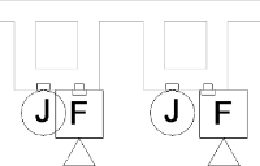
Figure21.12
shows how an offset parameter is used to achieve the desired display of
the annotations. The items on the left have interfering symbols because of
the locations of the device geometry. The items on the right are displayed
properly without affecting the device locations. (The device geometry is
visible only to show the offset.)
Figure 21.12
Symbol offset parameter used for proper device display
You can use this same functionality to create an offset that pulls the
annotation away from the device geometry or use both to create both
horizontal and vertical flexibility of the symbol. The offset plane or line can
be created directly in the device family only if the family is a nonhosted
type. For a face-hosted family, you need to have an offset defined in the
annotation family. The parameter that defines the offset can be associated
with a parameter in the device family for controlling the offset. See Chapter
18 for information on how to create an offset within an annotation family.
Having device families that are functional for both your 3D model and your
construction documents enable you to be more efficient with your design
andprojectcoordination. Nowthatyouhavelearnedaboutcreatingadevice
family with a nested annotation, practice the techniques to make a device
family usable in a project by completing the following exercise:
2. Click the Family Category And Parameters button located on the
Properties panel of the Create tab.
3. In the Family Category And Parameters dialog box, set the category to
Electrical Fixtures. Set the Part Type parameter to Junction Box, and