Graphics Programs Reference
In-Depth Information
can be used to control the visibility of the individual nested annotations,
giving you the ability to toggle between annotations when using the device
family in a project.
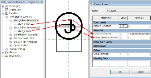
Figure 21.10
shows a device family with multiple nested
annotations.
Figure 21.10
Device family with multiple nested annotations
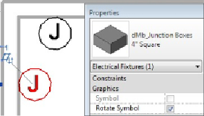
The Symbol parameter controls the visibility of the annotation for normal
orientation, and the Rotate Symbol parameter controls the visibility of the
rotated annotation. A formula was used so that, when you're working in a
project, you can select only one of the boxes for each instance, preventing
both annotations from being accidentally displayed. With this type of
behavior built into your device families, you can display devices in your
projects as desired.
Another method for controlling annotation behavior is to apply an offset
parameter so that the annotation symbol can be offset from the actual
location of the device. This is useful when two devices are next to each other
and their annotation symbols interfere. This can be done directly in the
device family by creating a reference plane parallel to the plane that defines
the left and right sides of the device. You can place this reference plane a
set distance from the origin plane of the device and pin it in place. This will