Graphics Programs Reference
In-Depth Information
Tab key to cycle through available faces that have a common edge. Once
you have highlighted the desired face, click to place the connector. There is
no need to dimension or constrain the connector because it is always in the
center of the selected 3D face.
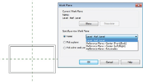
If you want to control the location of a connector, you can use the Work
Plane method of placement. This method requires that you select a plane on
whichtoplacetheconnector.Youcanuseanynamedreferenceplanewithin
the fixture family. Choosing the Work Plane option opens a dialog box with
optionsforspecifyingthedesiredplane.Youcanpicktheplanefromalistor
choose to select the plane manually.
Figure 20.21
shows the dialog box and
the various planes available in a sample lighting fixture family.
Figure 20.21
Work Plane : connector : placement dialog box
Once you have selected a plane for placement, the connector appears at the
insertion point of the family. You can then move the connector by selecting
it and using the Move command on the Modify | Connector Element
contextual tab. It is important to use the Move command because
attemptingtoclickanddragtheconnectoronlyrotatestheorientationofthe
Connector object.
After you have moved the connector to the desired location, you can convert
the temporary dimensions to actual dimensions to constrain the location of
the connector if necessary.
The properties of a connector determine how the fixture family behaves
electrically. The parameters of a connector can be associated with
parameters of the fixture family so that they can be changed parametrically