Graphics Programs Reference
In-Depth Information
Figure 19.36
Creating dimensions and parameters for the equipment
in plan orientation
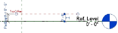
4. Open the Front elevation view. Draw a horizontal reference plane above
the Ref. Level. Select the plane, and name it
TopOfPad
in its element
properties. Create a dimension from the Ref. Level to the horizontal
plane. Create an instance parameter for the dimension called
PadDepth
; see
Figure 19.37
.
Figure 19.37
Creating dimensions and parameters for the equipment
in elevation orientation
5. Open the Ref. Level view. Click the Extrusion button on the Create tab
and sketch a rectangle. Align and lock the sketch lines to the reference
lines and planes. Click the green check mark button to complete the
sketch. Open the Front elevation view. Align and lock the top of the
extrusion to the TopOfPad reference plane drawn in step 4.
6. Click the Family Types button on the Properties panel of the Create tab.
Create a Yes/No instance parameter called
Pad
, grouped under
Construction, as shown in
Figure 19.38
.