Graphics Programs Reference
In-Depth Information
placement. This does not eliminate the need for dimensions or constraints;
it only takes them off the connector object itself.
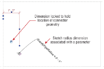
When you sketch a circle to create a cylinder, the point at which you draw
the center can be dimensioned while you are in sketch mode. This
dimension can be used for the location of the connector, as shown in
Figure
19.13
. The radius of the sketch can also be dimensioned and associated with
a parameter for easy size adjustment. Remember, when creating circular
connectors, use a circle for the sketch, not an arc that is copied/mirrored.
This is because the center point of the pipe connector will snap to the
centroid of one of the arcs, not that arc's center point.
Figure19.13
Geometry for cylindrical connector
Revit MEP 2013 was the first version to introduce the Diameter dimension.
This allows you to control round extrusions and connectors with one
parameter, and without the additional formulas that were required in the
past.
Reference planes or lines can also be used to determine the location of
the connection point geometry. This is easily done for pipe connections by
activating the Center Mark Visible parameter of the circle you are sketching,
as shown in
Figure 19.14
.