Graphics Programs Reference
In-Depth Information
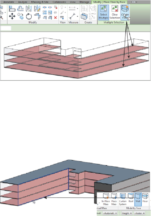
10. Click the Create Floor button. Floors are added to the model, as shown
in
Figure 17.47
.
Figure 17.47
Creating floors
11. Repeat steps 9 and 10 for the roof—except use the Roof By Face tool.
The walls are going to be treated in three separate stages: normal solid
walls, curtain walls, and curtain walls being used as windows.
12. In
Figure 17.48
,
you can see the placement for normal walls; select the
Wall button from the Model By Face panel of the Architect tab. Note
that the level and height of the wall are set to Automatic on the Options
Bar.
Figure 17.48
Creating walls
13. Make sure you have selected the correct wall type. Then select each face
of the mass, in turn, where you want a solid wall to appear. (The wall
type isn't extremely important because the analysis data for this
particular exercise is taken from user input, not the actual wall material.
However, glass will appear as an opening, as shown in
Figure 17.49
.
)