Graphics Programs Reference
In-Depth Information
3. On the Options Bar, set the depth of the extrusion to
0′-1/2″
(
12
mm)
and the number of sides to
4
.
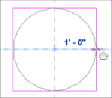
4. Click at the intersection of the reference planes to start the extrusion.
Drag your cursor to the right along the horizontal plane until the radius
is
1′-0″
(
300
mm), and then click to complete the sketch. See
Figure
Figure17.22
Sketch
5. Click the green check mark button on the Mode panel of the Modify |
Create Extrusion contextual tab to finish creating the extrusion.
Now we will create a blend that will be mounted on top of this
extrusion.
6. Click the Blend button on the Forms panel of the Home tab. Select the
Rectangle drawing tool from the Draw panel.
7. In the Properties box, set the First End constraint to
0′-1/2″
(
12
mm)
and the Second End constraint to
0′-1″
(
25
mm), and from the Options
Bar, change the Offset value to
0′-1/2″
(
12
mm). Select the upper-left
corner of the extrusion drawn in the previous steps and drag your
cursor to the lower-right corner, snapping to the end point at the
corner. If the sketch rectangle is on the outside of the first extrusion,
press the spacebar, which will flip the sketch orientation so that the
offset is to the inside (see
Figure 17.23
).