Graphics Programs Reference
In-Depth Information
chooseaviewwheretheprofilesketchcanbedrawn.Onceyouhavefinished
theprofile shape, youcan exit sketch mode byclicking thegreen check mark
button. You can then create the second profile by clicking the Select Profile
2 button and then the Edit Profile button.
Because you are defining each end of a swept blend solid with a profile
shape, you can create a twist in the solid geometry by locating the profile
sketches at different elevations from the plane of the path.
Figure 17.13
shows an example of a swept blend in which the profiles are drawn above
and below the plane of the path, creating a solid that not only changes shape
from one end to the other but also changes elevation.
Figure 17.13
Swept blend with profiles offset from the path plane
The file
Ch17_Modeling_SweptBlend.rfa
is provided as an example
and can be found at
www.sybex.com/go/masteringrevitmep2015
.
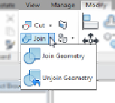
Joining Geometry
In some cases, it may be easiest to create a solid form by creating multiple
individual solids and then combining them. When you select an extrusion in
the Family Editor, the Geometry panel on the contextual tab contains tools
for joining geometry.
When you join geometry in the Family Editor, you create a union between
the selected solids; although they appear to be one, they are still separate,
editable forms. When geometry is joined, you can select all the forms by
placing your mouse pointer over one of the forms and using the Tab key