Graphics Programs Reference
In-Depth Information
When you click the Extrusion button on the Forms panel, the Modify |
Create Extrusion contextual tab appears on the ribbon. This tab contains
the tools needed to create the shape of the extrusion. The same drafting
tools that are available for any common drafting task are available when
you're sketching the shape for solid geometry. When you're working in
sketch mode, the reference planes and any other graphics in the view will
be displayed as a halftone, and the sketched linework will be magenta as a
visual indicator that you are working in sketch mode.
Thesketchyoudrawfortheshapeofanextrusioncanbeassimpleasacircle
or as complex as you can imagine. The most important thing is to create a
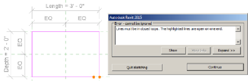
closed loop with no intersecting lines. You will receive an error message if
you attempt to finish a sketch that does not form a closed loop. The Error
dialog box allows you to continue sketching so that you do not have to start
over, or you can quit the sketch, which will discard the work done while in
sketch mode and return you to the Family Editor.
The sketch for an extrusion does not have to be a single, continuous set of
lines. You can draw several shapes for a single extrusion as long as each
shape is drawn in a closed loop. You cannot draw shapes that intersect
each other. When you draw one shape inside another, Revit will extrude the
area between the two shapes, as you can see in
Figure 17.1
,
which shows
one rectangle drawn inside another. This is a useful method for reducing
the need for void geometry in a family. Autodesk recommends avoiding
the use of too many voids in a family because this can adversely affect file
performance.