Graphics Programs Reference
In-Depth Information
is displayed. You can define the types of voltages available and also the
distribution system characteristics. This allows you to connect devices
properly and prevents you from accidentally wiring objects to the wrong
panel. You can set the visibility behavior of tick marks to show wire counts
and how wire tags display the electrical information. All of these settings are
project specific, so you can create a standard setup in your project template
based on company or project-type requirements.
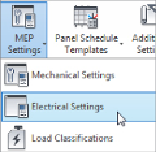
You can access the electrical settings at any time by typing
ES
or by clicking
the MEP Settings button on the Manage tab.
The Hidden Line settings in the Electrical Settings dialog box allow you to
establish the size of the gap that is shown when a conduit and cable tray
cross over each other. The gap size is relative to the scale of the views. These
gaps appear only when a view is set to Hidden Line mode.
The General settings determine how the electrical data is displayed for
devices and the format for describing the electrical characteristics. These
settings do not affect the behavior of electrical devices or circuits; they
affect only how information is displayed in the Electrical Data parameter of
devices. There are also settings for circuit naming if you name your circuits
by phase.
This section is also where you can define how load names are capitalized
in panel schedules. You can choose from the preset options provided.
Changing these settings after panel schedules have been generated does not
affect the existing load names in a schedule.