Graphics Programs Reference
In-Depth Information
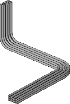
Figure 13.45
Parallel conduit runs
Placing Cable Tray in a Model
The process for modeling cable tray is the same as for conduit. There is
a drop-down on the Options Bar for the Width and Height settings of the
cable tray, as defined in the Electrical Settings dialog box. Cable tray can be
connected to equipment or devices that have cable tray connectors. Cable
tray connectors have a static location and cannot be moved along the face of
the family without editing the family.
You can connect conduit to cable tray by snapping your mouse pointer from
the cable tray edge when drawing the conduit. The conduit connects to the
center of the cable tray so, if you are using the Fine detail level setting, the
centerline of the conduit appears beyond the connected edge of the cable
tray, as shown in
Figure 13.46
.