Graphics Programs Reference
In-Depth Information
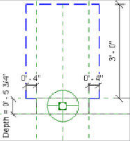
7. Dimension from the reference plane that defines the depth of the panel
to the clearance line parallel to it in front of the panel. Lock the
dimension.
8. Use the Save As command to save the panel family to a location of your
choice.
9. Create a new project file, and click the Wall button on the Architecture
tab to create a wall in plan view.
10. Load the new panel family into your project. Use the Electrical
Equipment button on the Systems tab to place an instance of the family
onto the wall.
11. Use the View tab, and click the Visibility/Graphics button. Once you're
in the dialog box, expand the Electrical Equipment category. Notice that
the Clearance Lines subcategory now exists in the project. Turn on the
display of electrical equipment, and click OK to close. You should now
see your family and clearance linework.
Assigning a distribution system to your panels is crucial to the intelligence
in your electrical model. This lets you create circuits for devices and lighting
fixtures as well as model the distribution system. The Distribution System
drop-down is available on the Options Bar when you place a panel into your
model.
Creating Similar Panels
If you use the Create Similar command to place a new panel in your
model that is just like another one, you still need to select a distribution
system for the new panel.