Graphics Programs Reference
In-Depth Information
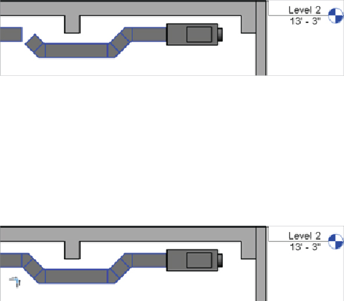
In
Figure 10.26
,
the duct has been split and a section created. To create
a duct set-down, you would hover over one end of the duct, right-click
the connector, and select Draw Duct. The duct would then be drawn
along the preferred route.
Figure 10.26
Editing duct in sections
3. Using tools such as the Trim command, you can complete the run, as
shown in
Figure 10.27
.
Bear in mind, sketching a duct in sections or
elevations must be done from connector to connector. Otherwise, the
work plane of the view will be where the duct is placed. In section and
elevation views, this is where the view's cut plane is. You see some
strange duct runs if you don't pay attention to that.
Figure 10.27
Completing the set-down
When creating ducts that set down/up or drop/rise, it can be much easier
to model these in a section or elevation view, as shown in
Figure 10.26
and
Figure 10.27
.
To do this, first you need to create a suitable view. Quite often,
individuals have a personal section that they move around the model. It can
be opened when required, and then the duct (or whatever service is being
worked on) is modified and the view is closed. This section, which should be
named for the individual, can then be used to show a quick 3D view of the
area using the Orient To View option.
Adjusting Fittings and Extending the Design
Changing the justification of ducts is a relatively easy task, but it can take
practice to actually master. Selecting a duct or a run of ducts/fittings gives
the user the option to change justification. Select your duct run, and from
the Modify tab, select Justify.