Graphics Programs Reference
In-Depth Information
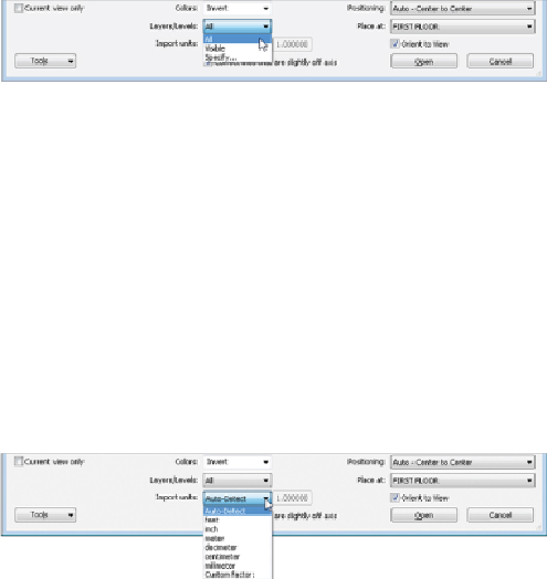
Figure 4.31
Layer options for a linked CAD file
Choosing the Specify option will open a dialog box from which you can
select the desired layers within the CAD file to load.
Layers within the linked CAD file can be removed after the file is in your
project by clicking the link in the view window and clicking the Delete
Layers button in the Import Instance panel.
3. Define the units for the file to be linked in. The Auto-Detect option,
shown in
Figure 4.32
,
causes Revit to use the unit setting that the CAD
file is using. This can lead to inaccuracy if the units in the CAD file are
not defined. The units can be modified in the properties of the linked
CAD file after it is placed into the project.
Figure 4.32
Import Units options for a linked CAD file
4. Position the CAD file. The positioning options for a linked CAD file are
the same as for a linked Revit file. If you are using shared coordinates
for your project, these coordinates need to be communicated to the civil
engineering consultant in order for the site plan to align properly. If
not, you can place the CAD file manually to line up the graphics.
Typically, the architect will provide a building outline to the civil
engineering consultant that will appear in the linked site plan and will
handle the establishment of shared coordinates. Whatever method is
chosen, be sure to pin the link in place to prevent accidental movement.
The Orient To View check box in the lower-right corner will position the
file appropriately, based on your view orientation, either Plan North or
True North.
If you choose to use the Import option instead of linking, the options for
placing the file are the same except for the automatic orientation to your
view. For the sake of good file hygiene, it is best to link CAD files instead