Graphics Programs Reference
In-Depth Information
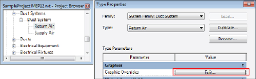
is not established in the Object Styles dialog box but rather in the type
properties of the system families, as shown in
Figure 2.9
.
Figure 2.9
Duct system graphic overrides
The display of the new placeholder categories can be defined in the Object
Styles dialog box, along with the lining and insulation categories that have
been added for both pipes and ducts.
Drafting Line Settings
In the same way that the Object Styles settings define how model,
annotation, and imported objects are displayed and printed, it is necessary
in a template file to define the various line styles that will be used for any
draftingordetailingthatmaybedoneinyourprojects.Alinestyleisdefined
by its weight, color, and pattern. You can create different combinations of
these settings to define lines that are used for specific drafting purposes or
that match your standards.
Line Weights
The first settings to consider when creating line styles are the available line
weights in your template file. You can access the Line Weights settings by
clicking the Additional Settings button on the Manage tab of the ribbon.
With Revit, you can establish 16 line weights. Typically, line weight 1 is the
thinnest line, and line weight 16 is the thickest. The Line Weights dialog box
has three tabs that give you access to the settings for lines, depending on
what type of view or to what objects the line weights are applied. The first
tabisformodelobjects.Modellineweightsaredependentonthescaleofthe
view in which they appear. You can define a thickness for each of the 16 line
weights as they appear in a specific view scale. This gives you the freedom to
show lines that are usually very thick as much thinner when the view scale
is larger.
Figure 2.10
shows the Model Line Weights tab of the Line Weights
dialog box. Notice that line weight 14 is half as thick in a 1/16″ scale view as