Graphics Reference
In-Depth Information
18. The results of normal mapping are visible in the right-hand side images of the tree
log render image in the
Adding surface detail with displacement mapping
recipe.
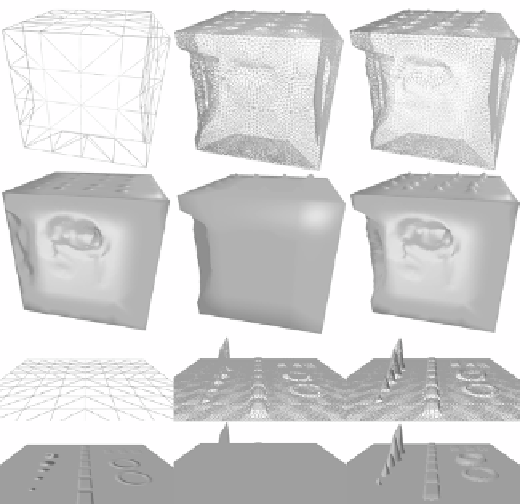
The following figure highlights the differences between normal mapping only (left),
displacement mapping only (center), and displacement mapping with normal
mapping (right).
Comparison of normal mapping (left), displacement mapping (center), and displacement mapping
with normal mapping (right). Cube displacement scale is 0.69, and plane displacement scale 0.5—tessellation
factor of 8.0 for middle and right.
How it works…
Using a normal map gives us additional directional information about a normal that allows us
to simulate surface detail. When viewed straight-on the illusion is quite convincing; however,
it falls short where there are silhouettes or contours (in the top-left cube in the previous figure,
the left edge and the top are obviously incomplete, whereas the side facing us looks correct).
Normal maps are usually in tangent space (also known as vertex space), which is aligned to
the tangent plane and normal vector at a vertex. The normal, tangent, and bitangent are all
vectors that are at right angles to each other (orthogonal). The tangent and bitangent are
usually used in relation to the texture map, with the tangent pointing along the u axis and
bitangent pointing along the V axis.