Graphics Reference
In-Depth Information
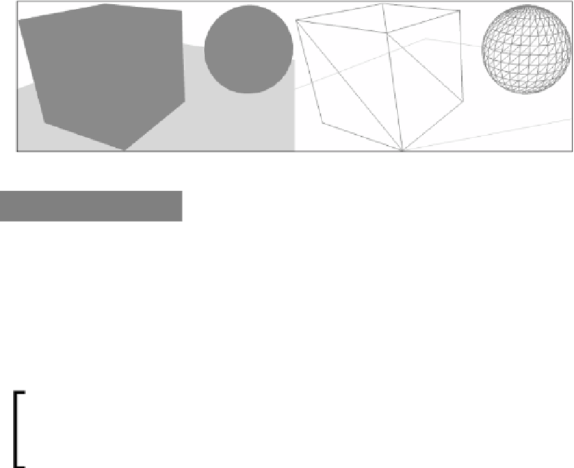
Now the quad, cube, and sphere will be visible with the quad being 5 times larger
than normal.
Scene after applying individual world translations - solid and wireframe
How it works…
The rendering of the cube and sphere is working in the same way as when we were rendering
primitives in the previous chapter. By combining a number of triangles together, we have
created our 3D mesh. However, we are now using a structure for the vertices.
By using a vertex structure, we now have more flexibility with what information can be
included with the vertex rather than relying on an array of floats. It is important that we
mark the structure using
LayoutKind.Sequential
and ensure that the data is packed
correctly so that it exactly matches the input layout definition.
By aligning the vertex buffer to 32 bytes, you may be able to slightly improve
the performance. In the example presented here, we would need to add
another 32-bit element (that is, 4 bytes) such as
Format.R8G8B8A8_
UNorm
as padding to both the input layout and the C# vertex structure.
We are now using a world matrix for each individual 3D object. As we already know,
rather than changing the vertices in each mesh and recreating the vertex buffers, we
use local object coordinates in the vertex buffer and then transform these in the vertex
shader using the WVP matrix. This means that we need to keep track of a world matrix
for each individual object or the hierarchy of objects so that we can continue to draw
them in the correct position/rotation/scale.
Try changing the scale of the sphere with the following code, and set the
rasterizer state to wireframe (
F-key
in the sample code) to see the impact
upon the mesh:
sphere.World.ScaleVector = new Vector3(1, 0.5f, 1);