Environmental Engineering Reference
In-Depth Information
Nest of
monitoring
wells
Nest of treatment
wells
Surrounding sheet-pile
wall
Direction of
groundwater flow
Optional treatment
zone with
enhanced NA
capabilities
Contaminated
region
Impervious clay layer
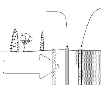
FIGURE 10.19
Containment of contaminants in a contaminated site using a conining sheet-pile wall that surrounds the
contaminated region. The sheet-pile wall is sunk into the impervious clay layer to prevent bottom escape of
contaminants. Treatment wells are sunk into the contaminated regions, and monitoring wells are placed down-
stream with some upstream also. Optional treatment zones using enhanced NA capabilities can be used, if
needed.
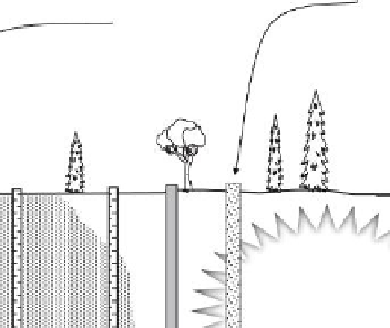
and if site hydrogeology is well understood, the solution shown in Figure 10.20 is one that
utilizes the capabilities of enhanced NA in combination of the permeable reactive barrier
(PRB) previously described. This procedure is both a mitigation and management tactic for
management of contaminant impact. Note again that the monitoring and treatment wells
are somewhat simplistic in illustrative portrayal.
The engineered barrier systems for a municipal and a hazardous waste landill shown
in Figure 1.11 are good demonstrations of the extent to which composite barrier systems
can be designed and engineered to meet the requirements for management and control of
contaminants. The details of the ilter, membrane, and leachate collection system are speci-
ied by regulatory
command and control
requirements or by performance requirements. In
the case of the MSW landill liner system shown in the bottom right-hand corner of Figure
1.11, the soil material comprising the engineered clay barrier underlying the synthetic
membrane must possess hydraulic conductivity values that are below the maximum per-
missible values. The basic idea in the design details of the engineered barrier for the MSW
landill is that if leachates inadvertently leak through the high density polyethylene mem-
brane (HDPE) and are not captured by the leachate collection system, the contaminants in
the leachate plumes will be attenuated by the engineered clay barrier. The engineered clay
barrier serves as the second line of defense or containment.
For the hazardous waste (HW) bottom liner system shown in the bottom left-hand cor-
ner of Figure 1.11, there are two lines of defense before the soil sub-base. The high-density
polyethylene (HDPE) acts as the irst barrier. Before this, the leachate collection system is

Search WWH ::

Custom Search