Environmental Engineering Reference
In-Depth Information
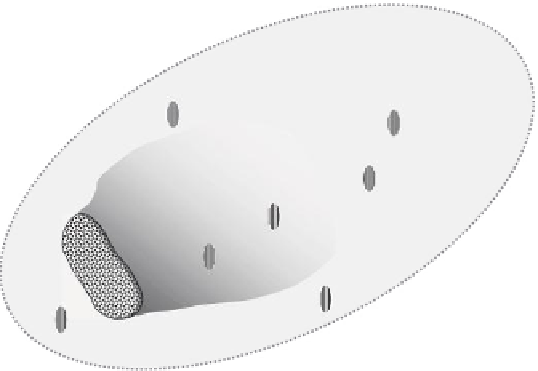
Management
zone
Multilevel soil sampling
Multilevel soil
sampling to
check outside
contamination
zone
Nest of monitoring and
sampling wells
Monitoring and
sampling wells to
check outside
contamination zone
Contaminant source
Contaminant plume
FIGURE 3.6
Plan view of distribution of monitoring wells and soil sampling boreholes for veriication monitoring and long-
term conformance monitoring. (From Yong, R.N. and Mulligan, C.N.,
Natural Attenuation of Contaminants in
Soils
, CRC Press, Boca Raton, 310 pp., 2004.)
can take the form of sorbates and co-precipitates. In turn, the sorbates can be complexed
with the soil solids and will remain totally ixed within the structure of the soil solids.
However, the sorbates can also be held by ionic forces, which can be easily disrupted, thus
releasing the sorbates.
What the preceding discussion of residence status of the contaminants tells us is that
we need to monitor and sample not only the porewater or groundwater but also the soil
fractions in the contaminant attenuation zone. Two types of monitoring-sampling systems
are needed. For porewater or groundwater, monitoring wells are generally used. These
wells are necessary to provide access to groundwater at various locations (vertically and
spatially) in a chosen location. The choice of type of monitoring wells and distribution or
location of wells will depend on the purpose for the wells. In respect to determination of
whether natural attenuation can be used as a treatment process, there are at least three
separate and distinct monitoring schemes that need to be considered. These range from
the initial site characterization studies to veriication monitoring and long-term confor-
mance monitoring.
The term
monitoring scheme
is used deliberately to indicate the use of monitoring and
sampling devices to obtain both soil and water samples. Figure 3.7 shows some typical
devices used as monitoring wells to permit monitoring groundwater at various levels. In
the left-hand group, we see individual monitoring wells with sampling ports located at
different depths but grouped together in a shared borehole. This is generally identiied
as a single borehole multilevel monitoring well system. The middle drawing shows a nest
of single monitoring wells in their own separate boreholes, and the right-hand drawing


Search WWH ::

Custom Search