Environmental Engineering Reference
In-Depth Information
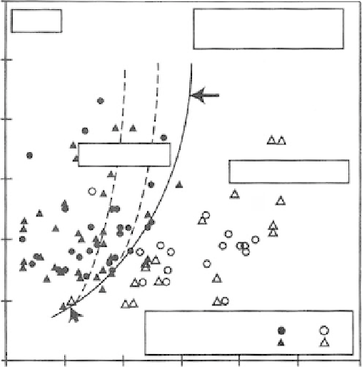
0.0
M = 7.5
0.25 <
D
50
(mm) < 2.0
FC (%) < 5
Y
e
≈
20%
≈
10%
≈
3%
0.5
CRR curve
0.4
Liquefaction
No Liquefaction
0.3
0.2
0.1
Field peformance
Stark & Olson (1995)
Suzuki et al. (1995b)
Liq.
No Liq.
NCEER (1996)
workshop
0
0
50
100 150
Corrected CPT tip resistance,
q
c1N
200
250
300
FIGURE 11.36
Liquefaction criteria based on CPT data. (From Robertson, P.K. and Wride, C.E.,
Proceedings NCEER Workshop
on Evaluation of Liquefaction Resistance of Soils,
Salt Lake City, Utah, 1997. Used with permission of the
Multidisciplinary Center for Earthquake Engineering Research, Buffalo, NY.)
Treatment for Liquefaction Prevention
Avoid construction
in seismically active areas underlain by loose fine-grained granular soils
where the water table may rise to within about 30 ft (10 m) of the surface, especially adja-
cent to water bodies.
Relatively shallow deposits
may be treated by excavation and replacement of the suscepti-
ble soils with engineered compacted fill, or by the support of structures on foundations
bearing on nonsusceptible soils.
Moderately deep deposits
may be treated by densification with vibroflotation or dynamic
compaction, by strengthening with pressure grouting, or by improvement of internal
drainage. The last may be accomplished with cylindrical, vertical gravel, or rock drains
(stone columns). A series of charts is presented by Seed and Booker (1977) which provides
a basis for the design and selection of a suitable drain system for the effective stabilization
of potentially liquefiable sand deposits by relieving pore pressures generated by cyclic
loading as rapidly as they are generated.
11.3.4 Slope Failures
Natural Slopes
General Occurrence
Seismic forces cause numerous slope failures during earthquakes, often as a result of
the development of high pore pressures. Such pressures are most likely to be induced in