Environmental Engineering Reference
In-Depth Information
Active wedge
w
1
Passive
wedge
w
2
L
2
α
1
T
2
2
U
2
N
2
T
2
I
CL
2
N
2
w
2
Force
polygon
tan
2
FS
δ
U
2
P
w
1
2
P
2
U
1
w
1
N
1
CL
1
tan
FS
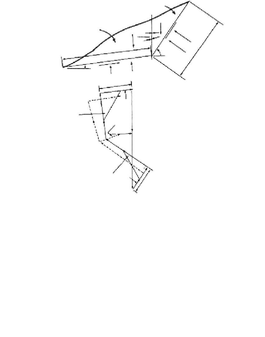
FIGURE 9.72
Forces acting on two wedges: one active, one passive.
W
1
,
W
2
are the weights of the wedge,
U
1
,
U
2
the resultant
water pressure acting on the base of the wedge,
N
1
,
N
2
the effective force normal to the base,
T
1
,
T
2
the shear
force acting along the base of the wedge,
L
1
,
L
2
the length of the base,
α
2
the inclination of the base to
the horizontal,
P
w
12
the resultant water pressure at the interface,
P
12
the effective force at the interface, and
α
1
,
δ
the inclination of
P
12
to the horizontal. (From Morganstern, N.R. and Sangrey, D.A.,
Landslides: Analysis and
Control
, Schuster and Krizek, Eds., National Academy of Sciences, Washington, DC, 1978, pp. 255-272.
Reprinted with permission of the National Academy of Sciences.)
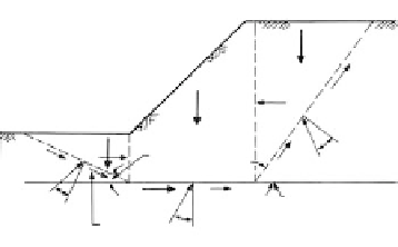
Active wedge
W
1
Central wedge
N
tan
P
A
W
3
Passive wedge
FIGURE 9.73
The general wedge or sliding block concept. (After
NAVFAC,
Design Manual, Soil Mechanics, Foundation and
Earth Structures,
DM-7.1, Naval Facilities Engineering
Command, Alexandria, VA, 1982.)
P
P
W
2
N
1
45
−
/2
c
C
c
45 +
/2
W
tan
N
2
N
2
tan
N
3
more accurate than the ordinary method, and slightly more accurate than the modified
Bishop's (1955) method.
Modified Bishop's method
: This is a simplified Bishop's method (Janbu et al., 1956), widely
used for hand calculations since it gives reasonably accurate solutions for circular failure sur-
faces. It is still widely used today on personal computers. The force system is given in
Figure
9.78c.
Janbu's method:
This is an approximate method applicable to circular as well as noncir-
cular failure surfaces, as shown in
Figure 9.79.
It is sufficiently accurate for many practical