Environmental Engineering Reference
In-Depth Information
Weathering
zone
1A and 1B
Slickensided fissures common
More permeable zone
Transition
11A
Clay seams
A
Joints
B
III
Thin sandstone
C
Shale mylonite
D
?
Bentonite seam
Layer thickening
FIGURE 9.31
Failure forms in weathered clay shales: (A) surface slump in shallow weathered zone; (B) wedge failure along
joints and sandstone seam; (C) wedge failure along thin bentonite seam may develop into large progressive
failure to (D) or beyond. (From Deere, D.U., and Patton, F.D.,
Proceedings of ASCE, 4th Pan American Conference
on Soil Mechanics and Foundation Engineering
, San Juan, P.R., 1971, pp. 87-170. With permission.)
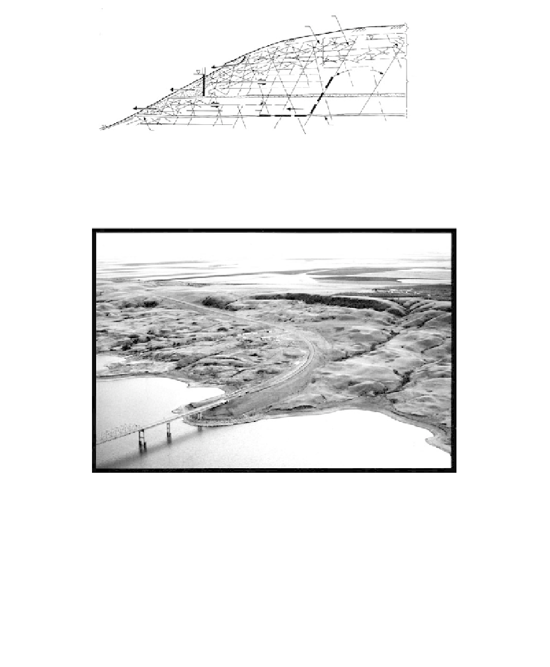
FIGURE 9.32
Aerial oblique, Forest City Landslide, South Dakota. Note the head scarp and hummocky landform. (Photo by
Vermon Bump, SDDOT.)
Aerial photos of the approach embankment are given in
Figure 2.8,
side-scan sonar images
of the reservoir bottom at the slide toe are given in
Figure 2.9,
and a typical geologic pro-
file is given in
Figure 6.90.
Slope failures probably began in early postglacial times when the Missouri River incised
its channel. Modern reactivation was caused by the filling of the valley with the reservoir,
and subsequent relatively rapid changes in reservoir water levels. The failing mass con-
sisted of a number of blocks, evidenced by surface tension cracks.
Stabilization of the overall sliding mass was essentially achieved by excavating a large
cut at the escarpment at the head and relocating the approach roadway into the cut. The
approach embankment, failing separately, was remediated by the installation of reinforced
concrete “dowels.”