Environmental Engineering Reference
In-Depth Information
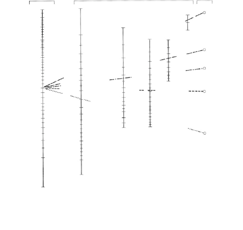
Groundwater
lowering,
ft
Spacing pf wellpoints,ft
Poles
2
Gravel
60
0.5
1
2
50
40
1
Gravel
3
1
1
Very fine
gravel
30
25
2
3
5
8
4
2
20
Coarse
sand
2
5
15
3
3
6
Medium
sand
4
Very fine
gravel
10
4
7
5
9
5
8
8
9
10
7
6
7
8
9
10
6
10
5
Fine
sand
15
4
Coarse
sand
Medium
sand
3
15
2
20
25
Fine
sand
1
FIGURE 8.42
Wellpoint spacing for uniform clean sands and gravels. (From Mansur, C.I. and Kaufman, R.I.,
Foundation
Engineering,
G.A. Leonards, 1962 and Moretrench Corp.)
condition to a strong, firm condition usually requires only a small change in pore pressure.
This is achieved by installing the wellpoint in the silt stratum and sealing the upper por-
tion of the well with clay (such as bentonite balls), as shown in
Figure 8.44.
If a sand layer
is affected by the system, the vacuum may not be applied effectively to the silt.
Jet-Eductor Wellpoint System
Noncohesive soils to depths of 50 to 100 ft (15-30 m) can be dewatered with a jet-eductor
system, useful for controlling uplift pressures in deep excavations. It is generally limited
to small yields from each wellpoint (less than 20-15 gal/min or 38-57 L/min). The system
consists of a wellpoint attached to the bottom of a jet-eductor pump with one pressure
pipe and one slightly larger pipe as shown in
Figure 8.45.
Deep Wells
Applications
Deep wells are necessary for deep, wide excavations, where the soil below the excavation
becomes more pervious with depth and the water table cannot be lowered adequately with