Environmental Engineering Reference
In-Depth Information
N
80
20
40
60
W
E
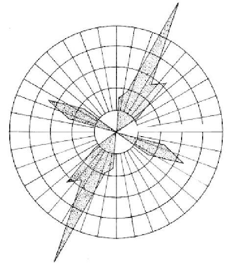
FIGURE 6.7
Joint rose or star diagram showing the
number of joints counted in each 10º sector
of a polar equal-area stereo-net. The plot
shows two sets of joints with average strike
about N25ºE and N65ºW. Plot is made only
when strike is determined. (From
Wahlstrom, E. C.,
Tunneling in Rock,
Elsevier,
New York, 1973.)
S
N
X
W
E
Y
S
FIGURE 6.8
A structural plane as visualized in orthographic
projection. (From Badgiey, P. C.,
Structural
Methods for the Exploration Geologist,
Harper &
Bros., New York, 1959. With permission.)
drawn through the center of the sphere and intersecting it as shown. The pole is found by
geometric construction and plotted on the net. (The meridians are marked off from the
center to represent dip degrees and the circles represent strike.) The procedure is followed
for other joints and the joint concentrations are contoured as shown in
Figure 6.13.
An
example of a Wulff net showing the plot of two joint sets in relationship to the orientation
of a proposed cut slope for an open-pit mine is given in
Figure 6.14.
The geometrical construction of stereo-nets and their applications are described in
texts on structural geology such as Badgley (1959), Hoek and Bray (1977), and FHWA
(1989).