Environmental Engineering Reference
In-Depth Information
b
a
a
j
25
30
a
c
e
30
a
30
80
80
b
b
60
d
c
10
20
d
c
k
b
d
f
c
80
(1)
(2)
(3)
d
l
a
d
g
80
b
e h
e
70
TA
c
f
i
m
(4)
a
b
c d
f
70
70
n
80
a
b
g
70
70
e
g
h
80
c
d
h
(5)
o
45
a
c e
i
40
p
f
i
j
b d
f
(6)
(7)
(8)
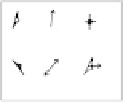
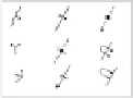
FIGURE 6.3
Symbols used on geologic maps. (From Lahee, F. H.,
Field Geology,
McGraw-Hill, New York, 1941.)
(1) Symbols used on maps of igneous rocks —
a
, flow layers, strike as plotted (N18ºE), dip 25º eastward;
b
,
flow layers, strike N45ºW, dip 60º NE (dips below 30º shown as open triangles; over 30º, as solid triangles);
c
, flow lines, trend plotted pitch 30º nearly north;
d
, horizontal flow lines, tend as plotted;
e
, vertical flow
lines;
f
, combination of flow layers and flow lines. (
After U.S. Geological Survey with some additions by Balk.
)
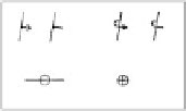
(2) Symbols for strata —
a
, strike plotted (N10ºE), 30º;
b
, strike plotted (N10ºE), dip overturned 80º. (These
symbols may be used with or without the arrowhead. In
b
, the strata have been turned through an angle of
100º, i.e., up to 90º and then 10º beyond the vertical.)
c
, strike east-west, dip vertical;
d
, beds horizontal.
(
After U.S. Geological Survey.
)
(3) Symbols for rock type combined with symbol for dip and strike —
a
, shale or slate;
b
, limestone, c,
sandstone;
d
, conglomerate.
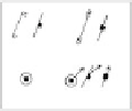
(4) Symbols used for a folded strata —
a
, general strike and dip of minutely folded beds;
b
, direction of pitch
of minor anticline;
c
, same for minor syncline;
d
, axis of anticline;
e
, axis of syncline;
f
, pitch of axis of major
anticline;
g
, same for major syncline;
h
, axis of overturned or recumbent anticline, showing direction of
inclination of axial surface;
i
, same for overturned or recumbent syncline. (
After U.S. Geological Survey.
)
(5) Symbols used for joints on maps —
a
, strike and dip of joint;
b
, strike of vertical joint;
c
, horizontal joint;
d
,
direction of linear elements (striations, grooves, or slickensides) on joint surfaces and amount of pitch of
these linear elements on a vertical joint surface. Linear elements are shown here in horizontal projection.
(
After U.S. Geological Survey.
)
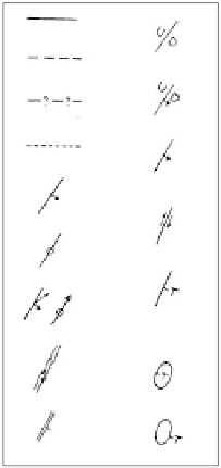
(6) Symbols used for cleavage and schistosity on maps —
a
, strike (long line) and dip (45º in direction of short
lines) of cleavage of slate;
b
, strike of vertical cleavage of slate;
c
, horizontal cleavage of slate;
d
, horizontal
schistosity or foliation;
e
, strike and dip of schistosity or foliation;
f
, strike of vertical schistosity or foliation.
(
After U.S. Geological Survey.
)
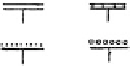
(7) Symbols for faults in sections —
a
to
d
, high-angle faults;
e
to
j
, low-angle faults.
a
, vertical fault, with
principal component of movement vertical;
b
, vertical fault with horizontal movement, block A moving
away from the observer and block T moving toward the observer;
c
, normal fault;
d
, reverse fault;
e
,
overthrust; f, underthrust;
g
and
k
, klippen or fault outliers;
i
and
j
, fenster, windows or fault inliers. (
After
U.S. Geological Survey.
)
(8) Symbols for faults on maps —
a
, known fault;
b
, known fault, not accurately located;
c
, hypothetical or
doubtful;
d
, concealed fault (known or hypothetical) covered by later deposits;
e
, dip and strike of fault
surface;
f
, strike of vertical fault;
g
, direction of linear elements (striation, grooves, slickensides, shown by
longer arrow) caused by fault movement, and amount of pitch of striations on vertical surface;
h
, shear
zone;
i
, strike and dip of shear zone;
j
, high-angle fault, normal or reverse, with upthrow U and
downthrow D shown;
k
, normal fault;
l
, reverse fault;
m
, relative direction of horizontal movement in shear
or tear fault, or flow;
n
, overthrust low-angle fault. T being the overthrust (overhanging) side;
o
, klippe, or
outlier remnant of low-angle fault plate (T, overthrust side);
p
, window, fenster, or hole in overthrust plate
(T, overthrust side). (
After U.S. Geological Survey.
)