Environmental Engineering Reference
In-Depth Information
(f) (e)
(e)
(a)
(a)
(L,o)
(r)
(o)
(o)
(o)
(r)
(o,L)
(a)
(t)
(t)
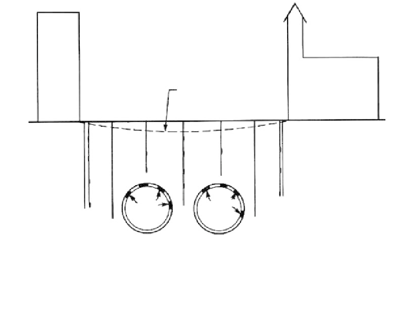
FIGURE 4.40
Instrumentation for tunnels in soil in urban areas. Legend: (a) precise leveling; (e) tiltmeter or (f) pendulum;
(L) inclinometer; (o) borehole extensometer; (r) piezometer; (t) load cells.
4.5.6
Natural and Cut Slopes
Case 1: Rock Cuts
Objectives
The basic objective is to maintain slope stability, which is related to steepness, height, the
orientation of weakness planes with respect to the slope angle, and cleft-water pressures.
Failure in rock slopes usually occurs suddenly, with rapid movement.
Slope Stability Problems
Natural slopes may become unstable from weathering effects, erosion, frost wedging, or
the development of high cleft-water pressures.
Open-pit mines are excavated with the steepest possible stable slope, and low safety fac-
tors are accepted for economic reasons. Instrumentation monitoring is generally accepted
as standard procedure for deep pits.
Hillside cuts for roadways and other constructions are usually less steep than open-pit
mine slopes in the same geologic conditions, and require a higher safety factor against fail-
ure. Evaluations are usually based on experience and empirical relationships, and instru-
mentation is normally used only in critical situations.
Instrumentation
(Figure 4.41)
Internal lateral movements are monitored in terms of displacement vs. time with incli-
nometers (L) and deflectometers (m) which can be attached to alarm systems, or with
borehole extensometers (o). Shear-strip indicators (n) and the acoustical-emissions device
(q) provide indications of mass movements.
External lateral movements are monitored with the convergence meter (g) or tiltmeter
(e) on benches, strain meters (h) on tension cracks, optical surveys (a) with the laser