Environmental Engineering Reference
In-Depth Information
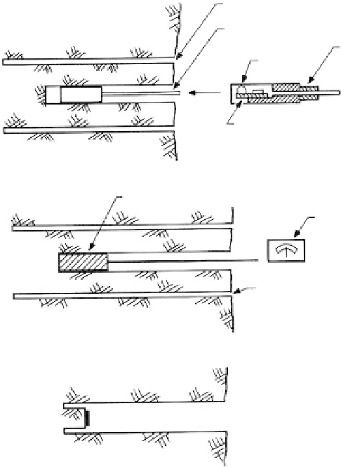
6-in. concentric borehole
1.5-in. borehole
Borehole
deformation
meter
Piston
Beryllium/copper
cantilever
(a)
Stress plug cemented to the wall of the hole
Stress-strain
measuring unit
connected to stress
plug
Trepanning hole to
relieve stresses
(b)
1
Set strain gage in
borehole with cement
Overcore borehole to
relieve stresses
1
2
2
(c)
FIGURE 4.33
Measurements of
in situ
stresses by stress relief in boreholes (a) borehole deformation meter; (b) high-modulus
stress plug or inclusion stress meter (a rigid or near-rigid device calibrated directly in terms of stress); (c)
Leeman “doorstopper” strain gage.
Procedure
The device is inserted into a small-diameter borehole (NX) and the stresses are relieved by
overcoring. These stresses are read directly with the inclusion stress meter, or computed
from strains measured with the deformation meter or strain gages. To compute stresses
when only strains are measured requires either a measurement or an assumption for the
rock modulus. Installation and interpretation are described by Roberts (1969). Maximum
applicable depths are of the order of 10 to 15 m because of the difficulties of making accu-
rate overcores, especially in holes that are not vertical.
Hydraulic Fracturing
Application
Hydraulic fracturing has been used to measure stresses in deep boreholes (Haimson, 1977)
and is still in the development stages.
Technique
A section of borehole is sealed off at the depth to be tested by means of two inflatable
packers. The section is pressurized hydraulically with drilling fluid until the surrounding