Environmental Engineering Reference
In-Depth Information
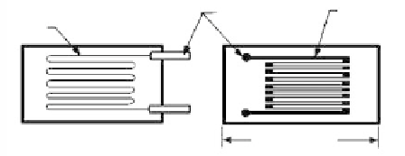
Fine-wire grid,
cemented to
backing
Lead-wire
attachments
Etched-metal
foil grid
FIGURE 4.1
Bonded resistance strain gages:
(a) wire grid, (b) foil grid.
Backing
1/16 to 6 in.
(a)
(b)
Unbonded, Encapsulated Gages
A fine wire is strung under tension over ceramic insulators mounted on a flexible metal
frame to form a resistance coil in unbonded, encapsulated gages
(Figure 4.2).
Usually two
coils are used and arranged so that one contracts while the other expands when the frame
is strained. The coils and the frame are factory-sealed into a tubular metal cover to provide
moisture protection. Mounting is achieved by bolting the gage to saddle brackets previ-
ously tack-welded or bolted to the measuring surface. The Carlson strain meter is one ver-
sion of the unbonded, encapsulated resistance gage.
Readouts
Strain indicators measure the resistance changes of the gages. They consist of a power sup-
ply, various fixed and variable resistors, a galvanometer, and a bridge circuit that can be
switched to connect the strain gages, resistors, and galvanometers in various configura-
tions.
Temperature Compensation
Temperature compensation is always required and can be achieved by a dummy gage
mounted so that it responds only to temperature-induced resistance changes or by the use
of self-compensating gages.
Vibrating-Wire Devices
Applications
Vibrating-wire devices are used for measurements of:
Strain with the transducer mounted on steel or embedded in concrete
●
Displacement and deformation with extensometers and joint meters
●
Tensile and compressive forces
●
Pore and joint water pressures
●
Changes in rock stresses
●
Changes in surface or subsurface inclinations
●
Temperature changes
●
Insulators
Fine wire
under tension
Lead-wire
attachment
FIGURE 4.2
Unbonded resistance strain gage. (From
Cording, E.J. et al., University of Illinois,
Urbana, Vols. 1 and 2, 1975. With
permission.)
Telescoping
tube with
bellows
8 to 20 in.