Environmental Engineering Reference
In-Depth Information
Estimating Values of E
s
Moduli for strain levels in the order of 10
6
can be estimated from shear-wave velocities
from crosshole or uphole seismic surveys (Swiger, 1974). Shear-wave velocities are used
because they can be measured above and below the groundwater level, whereas com-
pression-wave velocity can be measured only above groundwater level, since it is
obscured by the compression-wave velocity for water.
Under loads of the order of 2 to 3 tsf, strains in dense sands are small, approximately
10
3
, but higher than the strains occurring during seismic testing that require adjustment
for analysis. In granular soils,
E
d
and
G
d
have been found to decrease with increasing
strain levels (Hardin and Drnevich, 1972). A relationship between shear strain and axial
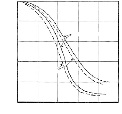
strain as a function of strain level is given in
Figure 3.91
.
The ratios given on the abscissa
are used to reduce the field shear and compression modulus for use in analysis.
Case Study
In a study reported by Swiger (1974), good agreement was found between settlements com-
puted from seismic direct surveys and large-scale
in situ
load tests and the actual settlements
measured on the structure for which the study was made. For a Poisson's ratio of 0.3, the val-
ues of
E
s
were of the order of 4
10
6
psf (2000 tsf). The primary settlements occurred within
about 1 h of load application, but the magnitude of the secondary settlement appeared to
approximate that of the primary and to continue over a period of some years. Approximately
25% occurred in the first year after load application (about 4-8 tsf foundation pressure).
Steady-State Vibration Methods
Purpose
Steady-state vibration methods are performed to obtain
in situ
values of
E
d
and
G
d
.
Principles
Ground oscillations are induced from the surface causing Rayleigh waves. The Rayleigh wave
velocity
V
r
is used directly as the shear-wave velocity because, for Poisson's ratios of 0.35 to
0.45,
V
r
0.935 to 0.95
V
s
, a difference which is of little engineering significance (Richart, 1975).
1.0
0.8
Shear strain
δ
0.6
0.4
FIGURE 3.91
Strain modulus relations for sands. (After
Seed, H. B.,
Proceedings of the 7th International
Conference on Soil Mechanics and Foundation
Engineering
, Mexico City, 1969; from Swiger,
W. F. ,
Proceedings of ASCE, Conference on
Analysis and Design in Geotechnical Engineering
,
University of Texas, Austin, Vol. II, 1974, pp.
79-92. With permission.)
Axial strain
ε
0.2
0
10
−
2
10
−
6
10
−
5
10
−
4
10
−
3
10
−
1
Strain