Environmental Engineering Reference
In-Depth Information
Inlet pressure
valve
Deviator stress
σ
d
Ram to apply load
A
σ
3
Transparent
material
container
Rubber
membrane
Soil
sample
σ
3
Manometer
Fluid
pressure
Porous
stone
Outlet
valve
T
T
FIGURE 3.49
Triaxial compression chamber
arrangement.
B
Sample drainage and water
pore-pressure connection
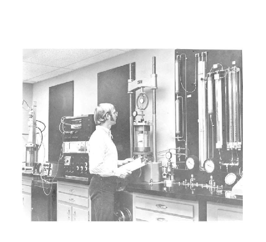
FIGURE 3.50
The triaxial compression chamber, load application, and measurement system.