Environmental Engineering Reference
In-Depth Information
A(
σ
n
,
τ
)
σ
1
−σ
3
τ
max
=
2
2
c
Normal stress
c
σ
nf
σ
3
σ
1
σ
3
+
σ
1
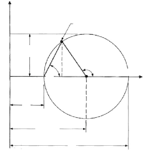
FIGURE. 3.22
The Mohr diagram relating
τ
,
σ
nf
,
σ
3
, and
σ
1
(
θ
cr
θ
at failure;
σ
nf
normal stress at failure).
approach
, i.e., a limiting value that can be reached when the forces acting to cause failure
are in balance with the forces acting to resist failure. Resistance to failure is provided by
the shear strength mobilized along the failure surface.
Typical Problems
Some field conditions involving failure by rupture are illustrated in
Figure 3.23,
showing
the relationships between the force acting to cause failure, the strength acting along the
failure surface, and the principal and normal stresses.
3.4.2
Shear Strength Relationships
Basic Concepts
Shear strength may be given in several forms, depending on various factors, including the
drained strength, the undrained strength, the peak strength, the residual or ultimate
strength, and strength under dynamic loadings. In addition, strength is the major factor in
determining active and passive Earth pressures.
Under an applied force, a specimen will strain until rupture occurs at some peak stress;
in some materials, as strain continues, the resistance reduces until a constant minimum
value is reached, termed the ultimate or residual strength.
Factors Affecting Strength
Material type:
Some materials exhibit only a frictional component of resistance
φ
; others
as well as cohesion
c
. In soft clays, at the end of construction, it is normally the
undrained strength
s
that governs.
Confining pressure:
In materials with
exhibit
φ
φ
acting, the strength increases as the confining
pressure increases.