Environmental Engineering Reference
In-Depth Information
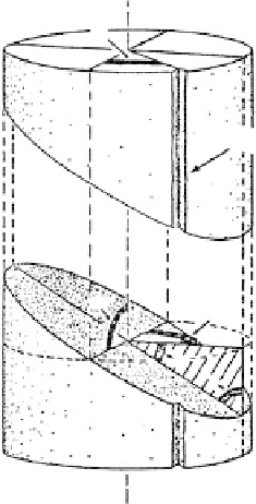
Scribe mark
Joint surface
90
°
90
°
δ
α
FIGURE 2.83
Oriented core with the joint surface intersecting the core wall at the joint
dip angle. The boundaries of a horizontal line across the joint are
located at angle ø providing the strike angle.
of 100% recovery with the orientation known. Defect orientation is an important factor in
rock-mass stability analysis.
Technique
1.
An NX-diameter hole or larger is drilled to where integral coring is to begin.
2.
A second, smaller hole (nominally about 1 in. [26 mm] in diameter) is drilled
coaxially with the first through the desired core depth, although usually not
exceeding 1.5 m in depth.
3.
A notched pipe is lowered into the hole and bonded to the rock mass with
cement or epoxy resin grout, which leaves the pipe through perforations.
4.
After the grout has set, a core is recovered by overcoring around the pipe and
through the cemented mass.
5.
During installation of the pipe, the notch positions are carefully controlled by a
special adapter and recorded so that when the core is retrieved, the orientation
of the fractures and shear zones in the rock mass are known.
Large-Diameter Cores by Calyx or Shot Drilling
Purpose
Calyx or shot drilling is intended to allow borehole inspection in rock masses in holes up
to 6 ft (2 m) in diameter.
Method
Calyx drilling uses chilled shot as a cutting medium. The shot is fed with water and lodges
around and partially embeds in a bit of soft steel. The flow of freshwater is regulated
carefully to remove the cuttings but not the shot. The cores are recovered by a special core-
lifter barrel, wedge pins, or mucking after removal of the core barrel. An example of a 36-
in.-diameter core taken in shale in which slickensides are apparent is shown in
Figure 6.54.
Limitations
The method is limited to rock of adequate hardness to resist erosion by the wash water and
to vertical or nearly vertical holes.