Hardware Reference
In-Depth Information
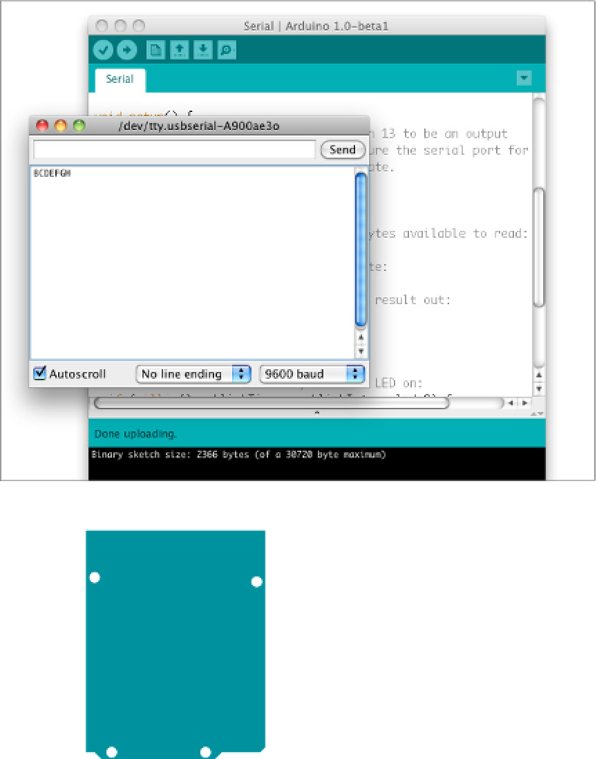
Figure 1-14
The Serial monitor in Arduino, running the
previous sketch. The user typed
BCDEFGH
.
AREF
G
ND
13
RESET-EN
12
RESET
3.3V
5V
Figure 1-15
Arduino connected to a breadboard. +5V and
ground run from the module to the long rows of
the board. This way, all sensors and actuators can
share the +5V and ground connections of the board.
Control
or
signal
connections from each sensor
or actuator run to the appropriate I/O pins. In this
example, two pushbuttons are attached to digital
pins 2 and 3 as digital inputs.
11
10
9
GND
GND
8
7
Vin
6
A
0
A
1
A
2
A
3
A
4
A
5
5
4
3
2
1
TX
0
RX
WWW.ARDUINO.CC