Hardware Reference
In-Depth Information
Once you've configured one of your radios, disconnect
your serial terminal program and unplug the board from
your computer. Next, remove the XBee from the circuit,
insert the second one, and configure it using the same
procedure. Don't set a radio's destination address to
the same value of its source address, or it will only talk
to itself! You can use any 16-bit address for your radios.
Here's a typical configuration for two radios that will talk
to each other (don't forget to add the
WR
to the last
command):
You can combine commands on the same line by separat-
ing them with commas. For example, to get both words of
a module's source address, type:
ATDL, DH\r
The module will respond with both words at once.
Likewise, to set both destination words and then make
the module write them to its memory—so that it saves
the address when it's turned off—type:
ATDL5678, DH0, WR\r
ATMy
ATDL
ATDH
ATID
The module will respond to all three commands at once:
Radio 1
1234
5678
0
1111
Radio 2
5678
1234
0
1111
OK OK OK
X
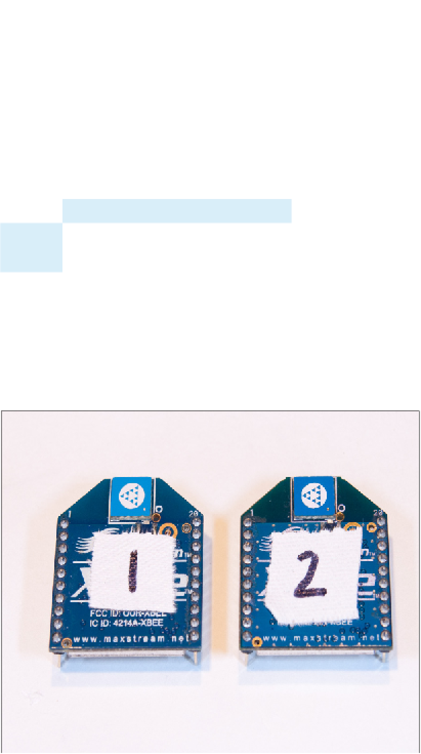
Figure 6-13
To keep track of the radios, label them
with a piece of tape. You'll be switching
them between the USB-to-Serial
adapter and the microcontroller a few
times, and it's easy to lose track of
which is which.