Environmental Engineering Reference
In-Depth Information
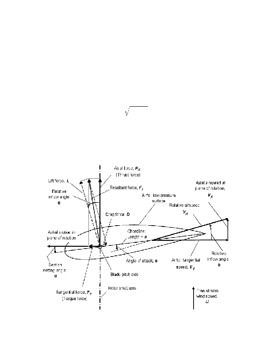
Aerodynamic Forces
Figure 2-13 illustrates the aerodynamic wind and force vectors acting on a section of a
rotor blade of a horizontal-axis wind turbine. In this simpliied example, the wind speed is
steady, the wind direction is parallel with the rotor shaft, the blade
pitch
(longitudinal) axis
is perpendicular to the shaft, and the blades section is perpendicular to the pitch axis. The
blade section moves tangentially forward in the plane of rotation and has no axial motion.
In a more general case, the blade sections may experience cyclic axial motions as a result
of elastic deformation and/or hinging. These cyclic velocities must then be added to or sub-
tracted from the axial airspeed (which itself may have cyclic components) when calculating
aeroelastic
fatigue loads.
The vectors in Figure 2-13 that relate directly to the estimation of rotor shaft power are
the
relative airspeed
, the
tangential force
(also called the
torque force
), and the
axial force
(also called the
thrust force
). The magnitudes of these vectors are calculated at discrete sec-
tions or
stations
along the length of the blade axis, usually at 5 percent to 10 percent intervals,
as follows:
V
X
+
V
Y
V
R
=
(2-11a)
V
X
= (1 -
a
)
U
(2-11b)
Figure 2-13. Diagram of wind and force vectors acting on a section of an airfoil.
Search WWH ::

Custom Search