Environmental Engineering Reference
In-Depth Information
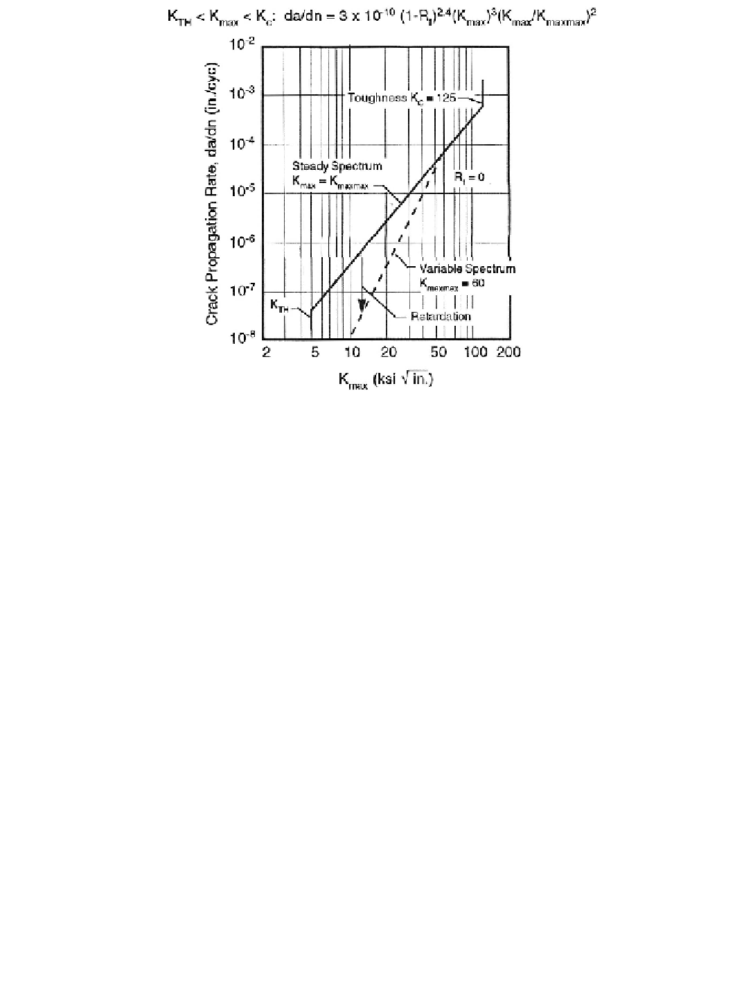
Figure 12-19. Sample crack-propagation rate model.
[Boeing 1988]
psi-in
0.5
, the latter property determined by test. The secondary line illustrates the effect of
occasional overloads (
i.e.
, load excursions) to a stress intensity of 60,000 psi-in
0.5
.
Sample Problem
Application of the fracture-mechanics method to the calculation of fatigue design allow-
able stresses in a wind turbine will be illustrated by a sample problem in which the following
parameters are speciied:
-- Material.................................................Category “B” weld in ASTM A-6 steel
-- Normalized Stress Spectrum................Table 12-1; 19,105 cycles
-- Design life time ....................................30 years, 330 spectra per year; 8 x 10
8
cycles
-- Initial crack size....................................Table 12-6, semi-elliptical surface law
-- Final crack size.....................................10 x Initial crack depth
-- Crack propagation model .....................Equations (12-17)
-- Overload stresses between spectra.......From 1.0 to 2.0 x
S
maxmax
Fatigue design allowables are to be calculated from these parameters and expressed in terms
of
S
maxmax
vs. S
overload
.
From Table 12-7, the initial crack dimensions are
a
= 0.050 in. and
c
= 0.125 in. The
crack is assumed to first propagate only in the depth direction, from its initial semi-elliptical
shape to a semi-circular shape of radius
a
= 0.125 in. Propagation then continues as a semi-
circular crack until
a
= 0.500 in., in accordance with the final crack size specification. Thus,
the shape factor in Equation (12-15b) is
Q =
1.200 - 0.714 (
a/c
)
2
if
0.050 £
a
£ 0.125 in.
Q =
0.486
if
0.125 £
a
£ 0.500 in.
(12-18)
Search WWH ::

Custom Search