Environmental Engineering Reference
In-Depth Information
Wind turbine components also experience the equivalent of a GAG cycle, in this case
the “start-run-stop” cycle shown in Figure 12-4. In addition, there are other types of fatigue
cycles which must be considered by the designer. One of these occurs at least once per rotor
revolution and is caused by gravity, wind shear (
i.e.
vertical gradient of the wind speed near
the ground), constant inflow distortion (
e.g.
tower blockage of the wind), and small-scale
turbulence.
Significant fatigue cycles on certain components can occur more often than once per
rotor revolution under two general conditions: (1) When the primary loading on the compo-
nent is related to the blade passage (
e.g.
, the yaw drive on a two-bladed HAWT), in which
case the number of fatigue cycles per revolution equals the number of blades, and (2) when
a resonance exists, in which case there are w/W fatigue cycles per revolution. Here w is the
natural frequency of the component and W is the rotor speed, and their ratio is typically three
or larger.
Small-scale and large-scale wind turbulence (such as gusts that envelop the entire rotor)
can cause fatigue cycles that are relatively independent of rotor revolutions.
Because of the complex nature of a load or stress time-history, a systematic procedure
is required for identifying and counting the individual fatigue cycles in a spectrum [ASTM
1990]. Several of these are evaluated using wind turbine field data by Murtha-Smith
[1985] and Bovarnick
et al.
[1985]. A counting method is usually selected for compat-
ibility with the analytical model used for predicting fatigue life. From the point of view
of fatigue life assessment, the cycle counting scheme cannot be separated from the fatigue
life model.
Early Method for Counting Fatigue Cycles
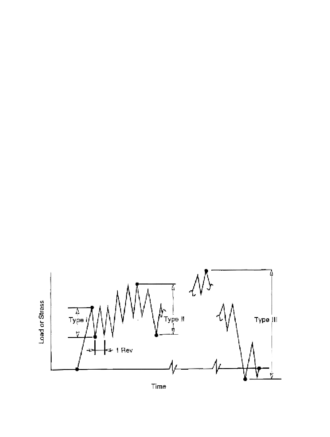
A simple cycle-counting model will be described here that was used successfully in the
design of the NASA/DOE Mod-1, Mod-2, and Mod-5B experimental HAWTs and in the
analysis of field test data from these and other turbines [Finger 1985]. As illustrated in Figure
12-5, a time-history of load or stress is assumed to be composed of three types of cycles:
--
Type I
:
Minimum to maximum during one or a part of one rotor revolution
--
Type II
:
Minimum to maximum during one large-scale change in wind speed
--
Type III
:
Minimum to maximum during one run, from startup to shutdown
Figure 12-5. Idealized types of fatigue cycles.
[Finger 1985]
Search WWH ::

Custom Search