Environmental Engineering Reference
In-Depth Information
and cost. Whatever the blade material, HAWT rotor hubs are almost always fabricated from
steel forgings, castings, or weldments.
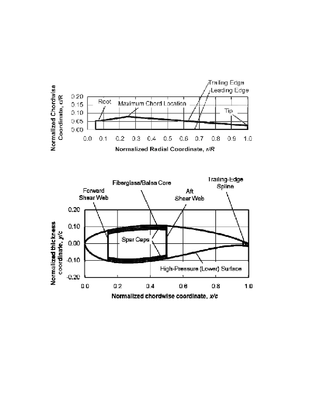
Figures 2-6 and 2-7 illustrate the basic shape of a modern wind turbine blade with full-
blade pitch. A typical
planform
shape [Grifin 2001] is shown in Figure 2-6, in which the
radial distance from the center of rotation,
r,
and the width or
chord
of the blade,
c,
are
normalized by the rotor tip radius,
R
. The airfoil section of the blade typically tapers from a
narrow chord at the tip to the maximum chord width at approximately 25 percent of the rotor
radius. Thus, the aerodynamic sections of the turbine blades cover about 94 percent of the
rotor swept area.
Figure 2-6. Typical normalized planform shape of a wind turbine blade.
[Grifin 2001]
Figure 2-7. Schematic view of the cross-section of a composite wind turbine blade,
showing typical internal structural elements.
[Grifin 2001]
A circular blade
root section
usually extends from a lange at approximately 5 percent
of the rotor radius where it is attached to the pitch-change mechanism in the hub, to approxi-
mately 7 percent of the radius where it transitions to the airfoil cross-section at the maximum
chord width. While this basic planform has straight leading and trailing edges and a squared-
off tip, advanced blade designs may add curvature to both leading and trailing edges to im-
prove performance. In addition, the blade tip is often shaped to reduce noise by rounding
leading and trailing edge corners.
Search WWH ::

Custom Search