Environmental Engineering Reference
In-Depth Information
C
L
,
C
D
=
lift and drag force coefficients, respectively; prescribed functions of a
a
= angle of attack, from the relative wind to the chord line (rad)
c
=
chord length of the airfoil section (m)
d
x
= increment of spanwise length (m)
We see from Figure 6-1 that the directions of the lift and drag forces are determined by the
direction of the relative wind and not by the blade geometry. As a result, lift and drag
directions will vary along the span of the blade and change with changing wind and
operating conditions, which is not convenient for structural analysis.
The force components of interest for structural analysis are those related to the principal
inertia axes of the entire blade. To locate these directions, we first define a
reference
station
along the spanwise axis of the blade. The reference station is any location of special
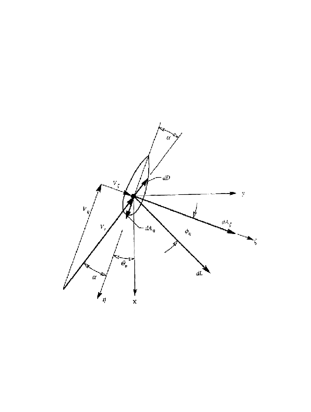
structural or aerodynamic interest. Referring to Figure 11-3, the angle between the cone
of rotation and the chordline at this reference station is defined here as the
pitch angle
,
q
p.
Figure 11-3. Velocity triangle at the blade reference station, and coordinate systems
used for computing aerodynamic loading.
The twist angle is zero. [Thresher
et al.
1986]
The chord line at the reference station becomes the h-axis. Next, we define a
reference
plane
as the surface generated by a h-axis line moving along the spanwise axis, remaining
parallel to the chord line at the reference station. Finally, we define the
twist angle
,
q
t
, as
the angle between the local airfoil chord line and the reference plane. The force
components of structural interest can now be expressed by
Search WWH ::

Custom Search