Environmental Engineering Reference
In-Depth Information
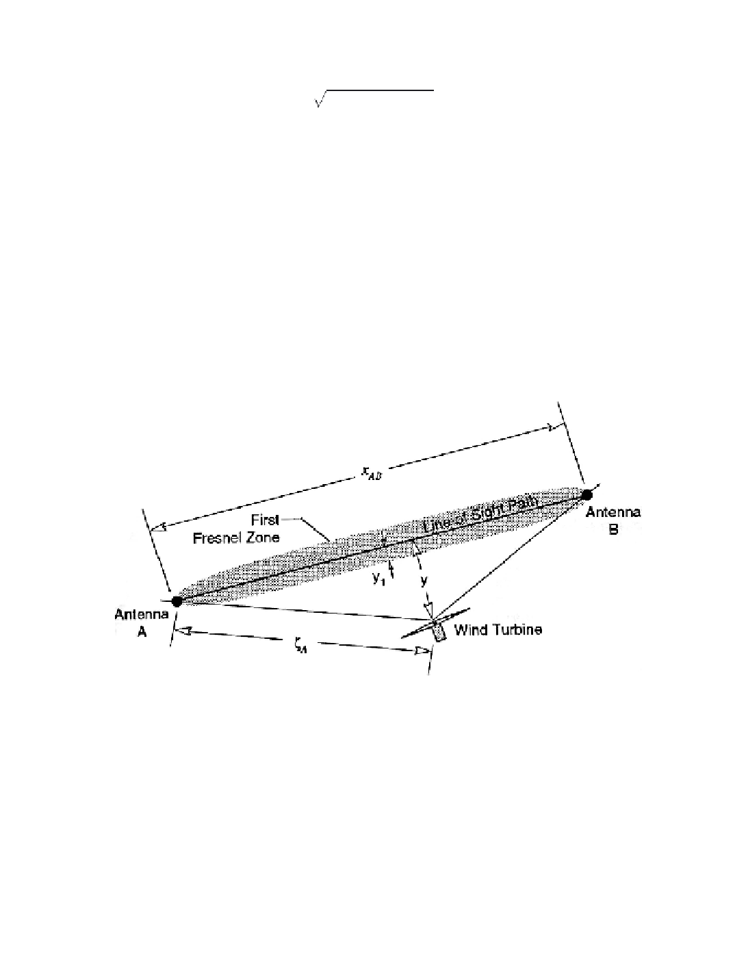
turbine. It
is often sufficient that all scattering objects lie outside the
first Fresnel zones
of the antennas in a microwave link [Bell Laboratories 1971, Griffiths 1987], as shown in
Figure 9-22. For any distance z
from antenna
A
,
the lateral distance from the link path
between antennas
A
and
B
to the boundary of the nth Fresnel zone is approximately
y
n
»
n
lz
A
(1 -z
A
/
x
AB
)
(9-33a)
y
min
= 3
y
1
(9-33b)
where
y
n
= width of the
n
th Fresnel zone (m)
n
= Fresnel zone number
z
A
= distance from the wind turbine to antenna
A
(m)
x
AB
= distance from antenna
A
to antenna
B
(m)
y
min
= minimum clearance between the link path and the wind turbine (m)
A clearance between the wind turbine and the link path equal to three times the width of
the first Fresnel zone is sufficient to ensure immunity from interference. In some cases it
may also be necessary to evaluate
m
R
to make sure that it is less than the appropriate
threshold value.
Figure 9-22. Schematic diagram showing a plan view of a wind turbine located outside
the first Fresnel zone of a link between two microwave antennas.
Antenna Azimuthal Response Factors
The azimuthal response pattern for a typical microwave antenna is highly directional,
as illustrated in Figure 9-23. This diagram represents the response function of a parabolic
dish antenna of the horn-reflector type, 2.4 m in diameter and shows the differences
between microwave and TV antenna patterns. It is obvious that to minimize interference,
a wind turbine must be outside the main beam and the near side lobes of a microwave
receiving antenna. Because of the very high back-to-front ratio of the dish, only forward-
Search WWH ::

Custom Search