Environmental Engineering Reference
In-Depth Information
P
R
=
G
O
F
A
(l/693p)
2
E
R
2
(9-8)
where
P
R
=
signal power
input
at the receiver location (mW)
G
o
= effective gain of the receiving antenna pointed at the transmitter mW/mV
2
)
F
A
= azimuthal response factor of the receiving antenna, dependent on f
A
;
F
A
£
1, with
F
A
(0)
=
1 (mW/mW)
f
A
= azimuthal angle from the receiving antenna beam to the signal source (rad)
l
= signal wave length = 299.8/
f
(m)
f
= carrier signal frequency (MHz)
Signal power is usually expressed in
dBm
or
dB above 1 mW
,
for which the definition is
(9.9)
P
R
(
dBm
) = 10 log
10
[
P
R
(
mW
)]
Effective gains for TV antennas range from about 4 to 16 mW/mV
2
(
i.e.
6 to 12 dB).
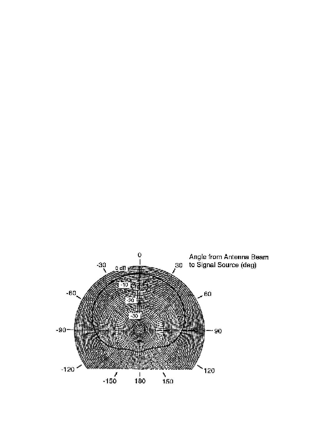
Figures 9-2 and 9-3 show typical azimuthal response functions for a directional antenna
used extensively for field evaluation of TV interference. Figure 9-2 presents the results of
a laboratory test in the form of a polar diagram for one signal frequency. The azimuthal
response function
F
A
(in dB) is equal to the difference between the reading at a given
antenna direction and that at zero degrees. In Figure 9-3, the results of a field test of the
same antenna at the same frequency are compared to the laboratory data, showing the
effects of local terrain and atmospheric conditions.
Figure 9-4 shows typical modulations of an audio power signal that can be caused by
the addition of a secondary signal scattered by a HAWT rotor. In this case the turbine is
the 2.0-MW Mod-1 machine with two steel blades rotating at 10 rpm, which produces a
modulation wave form with a period of 3.0 s [Sengupta
et al.
1981a]. In Figure 9-4(a), the
antenna beam is pointed at the wind turbine, at an azimuth of 288 deg. The direct (desired)
signal on Channel 3 is received from the transmitter at an azimuth of 154 deg. Thus,
Figure 9-2. Typical azimuthal response factors for a directional TV antenna, as mea-
sured in the laboratory.
Frequency = 63 MHz (Ch. 3) [Sengupta
et al.
1981a]
Search WWH ::

Custom Search