Environmental Engineering Reference
In-Depth Information
Sources (Greece) greatly advanced the state of the art for performing research grade measure-
ments in the field environment. Data acquisition and documentation was carried out under
the auspices of International Energy Agency Wind R&D Annexes XIV [Schepers
et al.
1997]
and XVIII [Schepers
et al.
2002].
Need for Inflow Control and Wind Tunnel Testing
However, improved field measurement systems and enhanced data quality accentuated
a long standing dilemma. Large scale turbines could be thoroughly instrumented, but size
constraints required testing in the atmosphere. There, wind inflow fluctuations introduced
uncertainties that precluded unambiguous characterization of key aerodynamic phenomena.
Alternatively, wind tunnels offered controlled inflows, but severely limited test turbine size.
Disparities between wind tunnel and field turbine sizes led to uncertainties regarding the
validity of extrapolating wind tunnel measurements to larger-scale turbines.
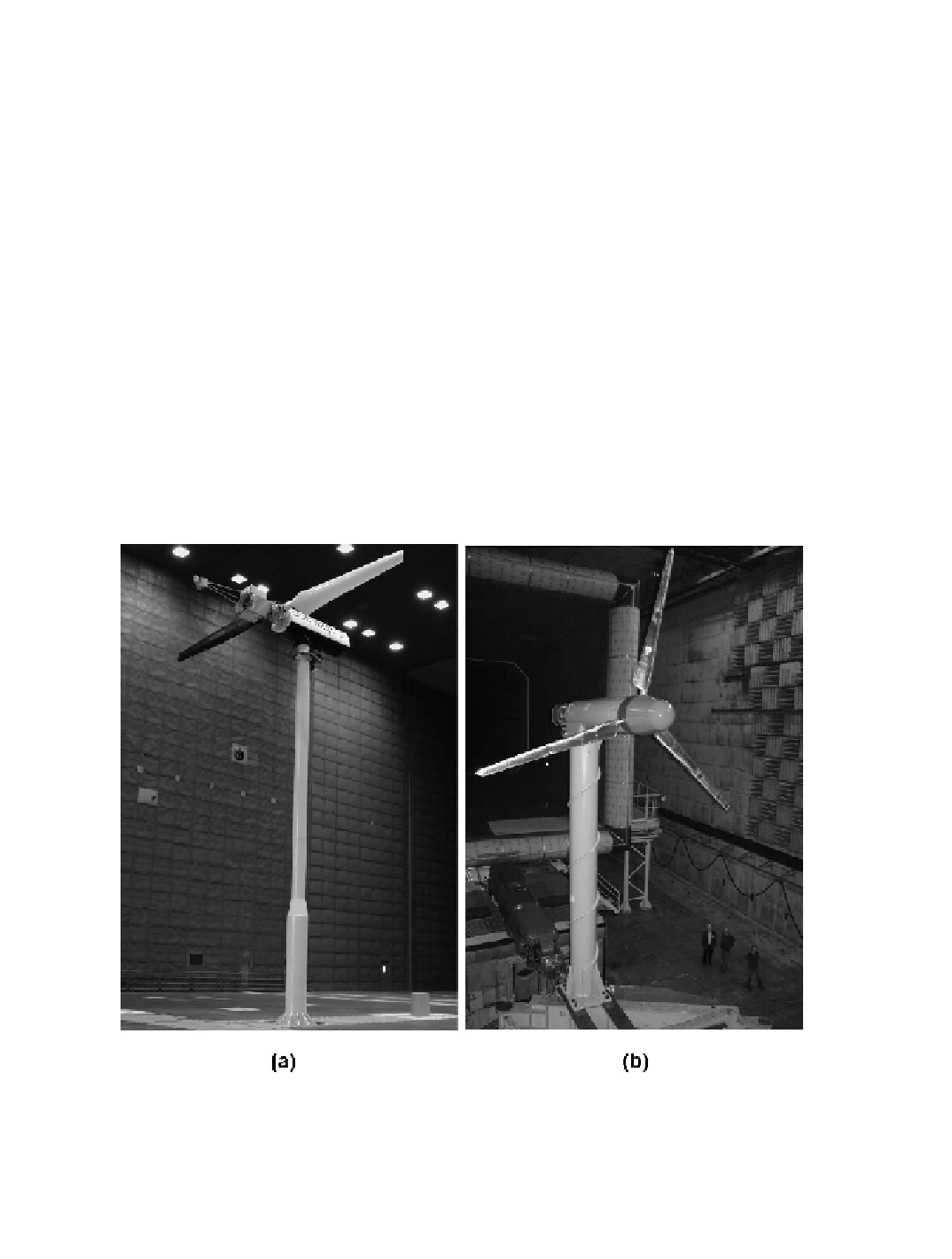
In the U.S., resolving this dilemma led to the design and construction of an NREL test
turbine designated as the
Unsteady Aerodynamics Experiment Phase VI
HAWT
(UAE Phase
VI), Fig. 5-44(a), which was tested in the NASA Ames 24.4 m x 36.6 m wind tunnel [Hand
et al
. 2001]. The rotor configuration of the UAE Phase VI turbine was two-bladed, constant
speed (72 rpm), mounted upwind of its support pylon, and stall regulated. Its 5.03-m (16.5-ft)
rotor radius included a tapered, twisted blade and hub. A 21percent thick, NREL S809 airfoil
was used along the blade except for the cuff region, which transitioned from the circular root-
end fitting to the S809 airfoil at 25 percent span [Tangler and Kocurek 2004].
Figure 5-44. Wind turbines specifically designed for detailed aerodynamic testing in
wind tunnels. (a) UAE Phase VI turbine mounted in NASA Ames 24.4 m x 36.6 m wind
tunnel. (b) MEXICO turbine mounted in DNW LLF 9.5 m x 9.5 m wind tunnel.
Search WWH ::

Custom Search