Environmental Engineering Reference
In-Depth Information
Flow Model
The foremost assumption in strip theory is that individual
streamtubes
or
strips
(the
intersection of a streamtube and the surface swept by the blades) can be analyzed indepen-
dently of the rest of the flow. Such an assumption works well for cases where the circulation
distribution over the blade is relatively uniform, so that most of the vorticity is shed at the
blade root and the blade tip. The deployment of
control surfaces
, however, can violate this
assumption. For example, the use of
partial-span pitch control
on a HAWT rotor introduces
discontinuities in circulation, and appreciable vorticity can be shed near the junction between
the inboard blade and the moveable tip. Fortunately, control surfaces are usually deployed
to spill excess power at high wind speeds, when the induced velocity is relatively small.
Thus, calculation errors that arise when strip theory methods are used to analyze rotors with
deployed control surfaces are not usually significant.
A second assumption associated with the development of strip theory is that
spanwise
flow
is negligible, and therefore airfoil data taken from two-dimensional section tests are ac-
ceptable. Strip theory does not predict any induced flows along the blades. However, when
a blade is not perpendicular to the axis of rotation (
e.g.
, when the blade has a
coning angle
)
the wind has a component that is directed along the span of the blade. This component is
neglected and two-dimensional flow is assumed, adding some error to the airfoil data. A
third assumption is that flow conditions do not vary in the circumferential direction. With
this assumption, the “strip” to be analyzed is a uniform annular ring centered on the axis of
revolution.
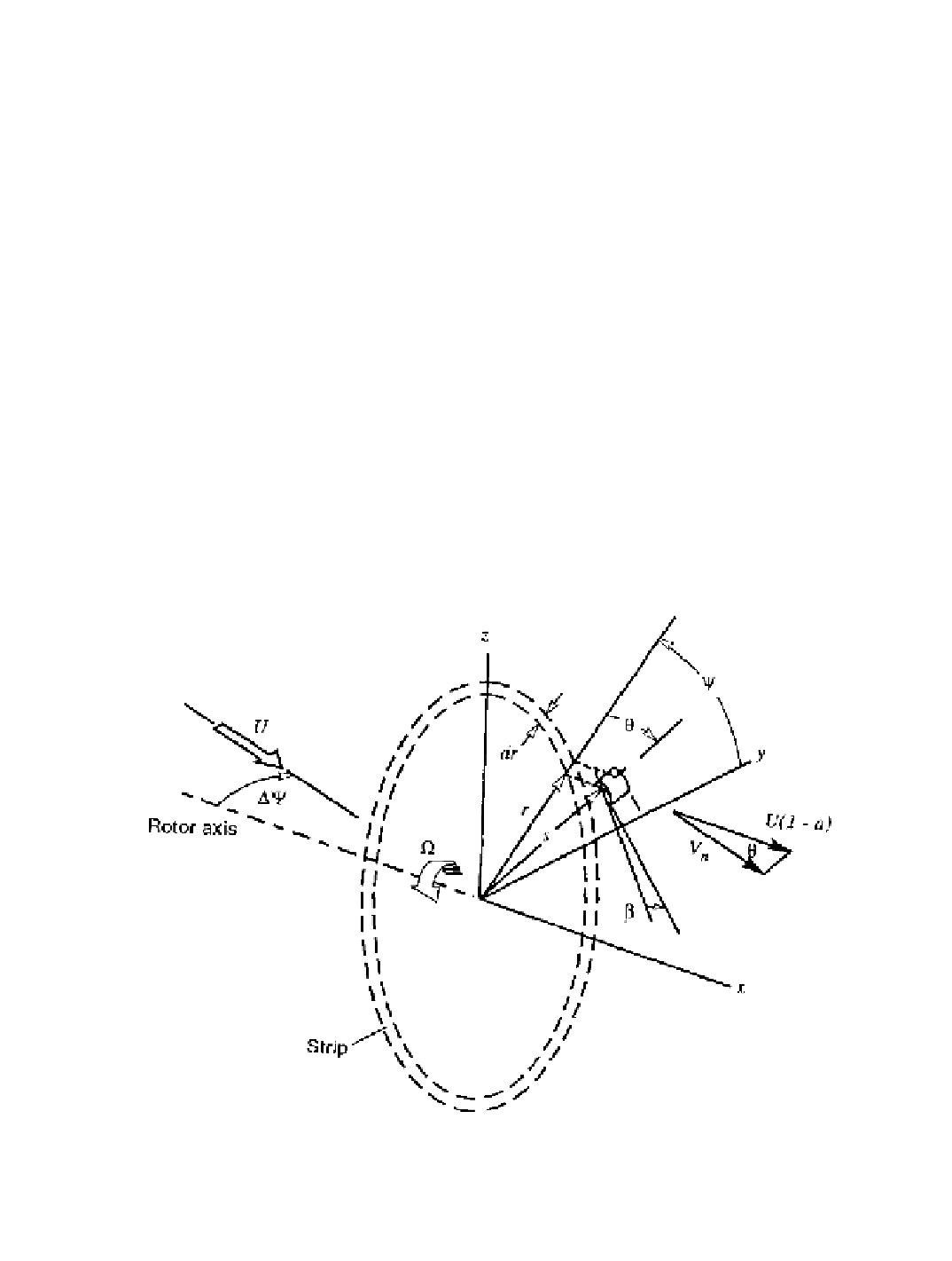
Figure 5-12 shows the strip geometry and the coordinate system used. Note that the
coordinate
s
is measured along the blade and
r
is at right angles to the rotor axis. The wind
velocity,
U
, is assumed to be constant in time and space and aligned with the axis of rotation,
so that the
yaw error
, DY, is zero. When the rotor blades are coned, the velocity diagram in
Figure 5-12. Strip geometry and coordinate system.
Search WWH ::

Custom Search