Environmental Engineering Reference
In-Depth Information
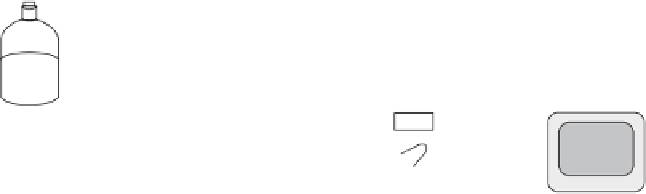
Solvent
reservoir
Injector
308
Column
Pump
Column thermostat
Detector
Waste
Figure 10.4
Schematic diagram of a typical HPLC system (Girard, JE, Principles of Environmental
Chemistry, 2005, Jones and Bartlett Publishers, Sudbury, MA.
WWW.jbpub.com.
Reprinted with
permission.)
HPLC, solvent properties that are fundamental to the HPLC method development
are also introduced.
Solvent reservoirs contain either neat liquids, mixtures of liquids, or liquids
with modifiers such as buffers. These solvents must have a purity of ''HPLC'' grade
or higher, and must be free of particles and dissolved gases. Particles must be
removed by filtering solvents through 0.25-
m filters. Doing so will extend the pump
life by preventing scoring and reducing contamination or plugging of the column. A
replaceable inlet filter inside each solvent container is also commonly used to further
protect particular matter or residual salt from entering into the system. Dissolved
gases in solvents are detrimental to the HPLC system because they result in bubbles,
low pressure, noise, and inaccurate flow. Dissolved gases are removed by a
degassing unit, which can be a sintered glass connected to a helium gas cylinder
(sparging), or an online vacuum degassing system in which solvent passes through a
thin-walled porous polymer tube in a vacuum chamber.
Solvents in the reservoirs are drawn by a corrosion resistant pump capable of
delivering high pressure, pulse free, accurate flow rate of solvents. The mobile phase
solvents are then forced through an analytical column for compound separation,
where high pressures are developed. In HPLC system, the pressure between the
pump and detector are high. Typically, pressures of 1000-3000 psi (1000 psi 70
bar) are required to provide flow rates of 1-2 mL/min in columns of 3- to 5-mm i.d.
and 10-30 cm long. The usual type of HPLC pump is the so-called short-stroke
piston pump. Pumps should never run dry. Purging or priming may be done when
needed to remove gas bubbles in HPLC system with higher flow rates of mobile
solvent. Flush the pump tubing with solvent when the pump chamber and the inlet
lines from the solvent reservoir are empty. This usually occurs after the pump has
been idle for a while.
Liquid samples are introduced into a sample injection system located between
the pump and column by either manually filling the sample loop with a syringe, or
with an autosampler having 6-port values. In addition to the components shown in
Figure 10.4, a pressure transducer,anin-line filter, and a guard column are always
m


Search WWH ::

Custom Search