Environmental Engineering Reference
In-Depth Information
where many processes occur, some of which are very poorly understood;
in addition, the formations of interest are vast (hundreds of square kilom-
eters in areal extent) and remote (
800 m deep). The characterization of
potential carbon sequestration sites is expensive (the drilling of charac-
terization wells can constitute a major portion of carbon sequestration
project costs) and accordingly incomplete.
>
Simulation grid
With the exception of a few studies that rely on models that employ ana-
lytical solutions to the CO
2
-brine multiphase fl ow equations in simplifi ed
geometries, most fi eld-scale carbon sequestration models and all mod-
els that couple multiphase fl ow and geochemistry use numerical meth-
ods that rely on a discretization of space into an ensemble of fi nite size
simulation grid blocks, each treated as a well-mixed reactor (
Figure 10.2.3
)
[10.4]. During each time step, the model successively calculates the pro-
cesses that occur within each grid block and the fl uid fl uxes between
neighboring grid blocks. Grid block dimensions typically are on the order
of 1 to 10 m vertically and 10 to 100 m horizontally. Each grid block
50 years
-1800
0.7
0.5
0.4
0.3
0.2
0.1
-2000
-2200
-2400
704 706 708 710
Northing (km)
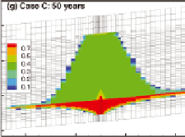
Figure 10.2.3
Prediction of CO
2
saturation near an injection well
Model prediction of CO
2
saturation near an injection well in the Illinois Basin after
50 years of injection at the rate of 5 megatonne CO
2
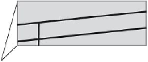
per year. The simulation grid is
shown by the thin gray lines. Each grid block is 20 to 1,000 m wide (increasing with
distance from the well) and up to 10 m high. The inset shows a schematic view of a grid
block as a well-mixed reactor (shown by the mixing paddle) that exchanges fl uids with
the surrounding grid blocks (shown by the arrows).
Figure reproduced from Zhou et al,
with permission from John Wiley and Sons
[10.4]
.


Search WWH ::

Custom Search