Environmental Engineering Reference
In-Depth Information
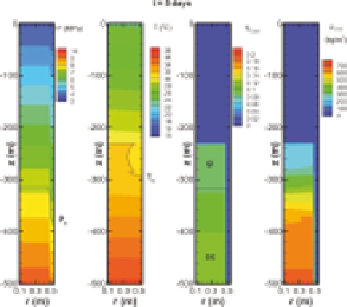
(a)
(b)
(c)
(d)
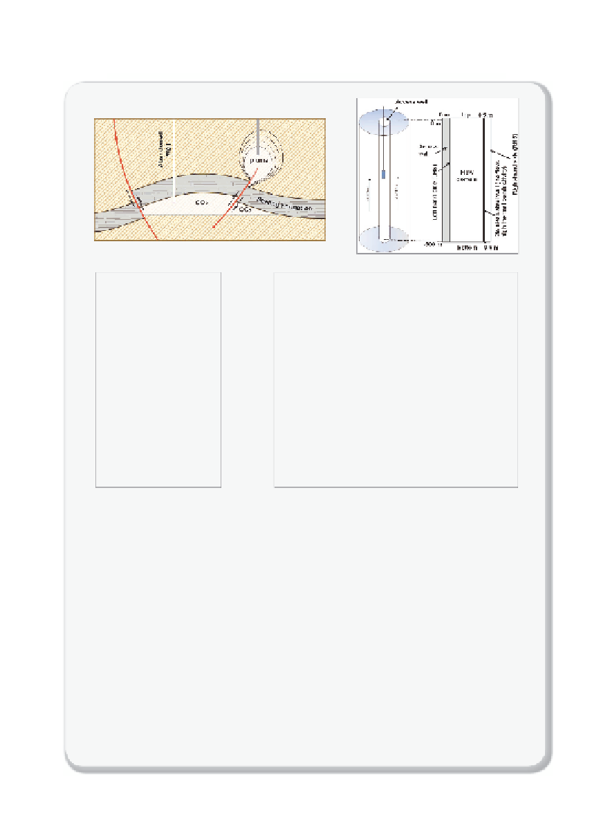
Figure 9.3.2
Stimulation of the upwelling of CO
2
(a) The caprock or seal is preventing the injected CO
2
to move upward. In some cases
(see Chapter 10 for more details), faults or abandoned wells can be leakage path-
ways for CO
2
in these simulations, we are interested in simulating the fl ow in the rock
formation as indicated by the grey cylinder, above the CO
2
plume that is escaping
through a fault. In the movies, the effect of heat transfer on the behavior of CO
2
is
studied: in
Movie 9.3.1
, heat that is generated during the expansion is dissipated,
while in
Movie 9.3.2
the walls of the cylinder are insulated.
(b) Sketch of the 500 m deep and 1 m wide column. In the simulations, the column is
assumed to be fi lled with sand.
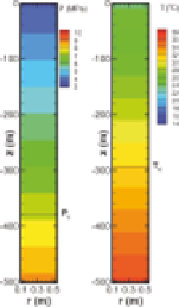
(c) Initial conditions for the system are fully brine-saturated (no CO
2
present). The fi gure
shows with a color coding the hydrostatic
P
(left) and geothermal-gradient
T
(right)
profi les in the column.
(
Continued
)


Search WWH ::

Custom Search