Environmental Engineering Reference
In-Depth Information
description becomes less useful and we have to use a more coarse-
grained description.
Before we can discuss the physical and chemical processes that
govern geological sequestration, we have to go back to the basics: we
need to refresh our understanding of different rock types, how geological
formations are formed, and the properties of fl uids in these formations.
Section 2
Rocks
In the last chapter, we saw that different options are available for geologi-
cal storage of CO
2
. Of these options, deep saline water-saturated reser-
voir rocks (deep saline aquifers) have the largest capacity, which is one
of the reasons we focus on these formations in this chapter.
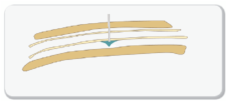
In
Figure 9.2.1
,
we illustrate the injection of CO
2
in a saline aquifer.
CO
2
is typically injected at a depth of 800 meters or deeper. In selecting
a storage formation, we need to ensure that it has a suffi ciently large rock
pore volume at this depth to store the amount of CO
2
we are planning to
inject. We need to ensure that this pore volume is connected so that the
CO
2
can access the entire aquifer from a single or a small number of
top seal (caprock)
> 800m
depth
reservoir rock
Figure 9.2.1
Schematic cross-section of a sequestration site shortly after beginning
CO
2
injection


Search WWH ::

Custom Search