Environmental Engineering Reference
In-Depth Information
10% CO
2
90% N
2
5 atm
Permeate
1 atm
Figure 7.3.1
Single-stage membrane for carbon capture
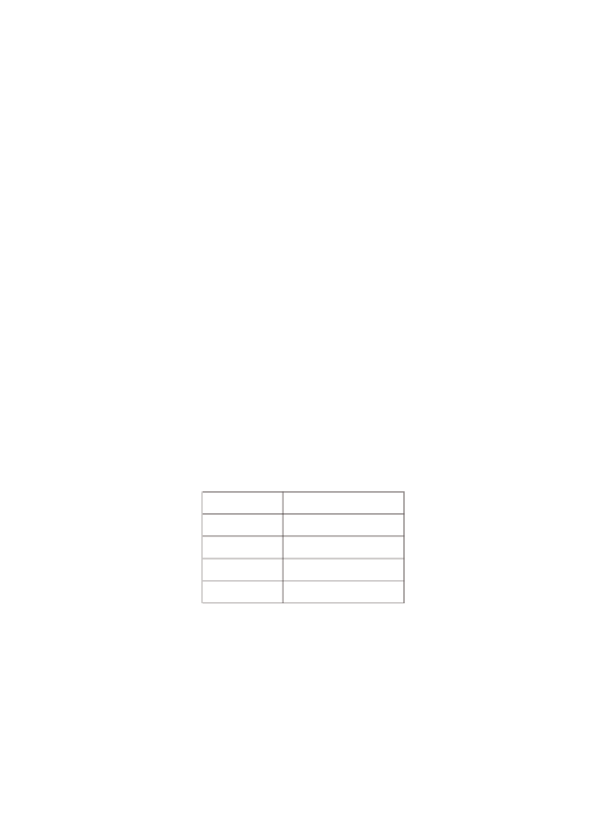
Table 7.3.1
Typical conditions for a membrane separation of fl ue gas
p
F
5 atm
p
p
1 atm
500 m
3
/s
Φ
F
x
CO
2
,
F
0.1
P
′
CO
2
1,000 gpu
p
F
— pressure of the flue gas,
p
P
— pressure of the permeate,
P
′
CO
2
— permeance of the mem-
brane where gpu
=
(10
−
6
cm
3
(STP)/cm
2
sec cm-Hg),
x
CO
2
,
F
— flue gas composition, and
Φ
F
—
emissions of flue gas.
membrane independently. For example, we can increase the selectivity
of our membrane by decreasing the N
2
permeability of our membrane
while keeping the permeability of CO
2
fi xed.
As we saw in the previous section, the values in
Table 7.3.1
together
with the selectivity fully specify our membrane and we can use the


Search WWH ::

Custom Search