Environmental Engineering Reference
In-Depth Information
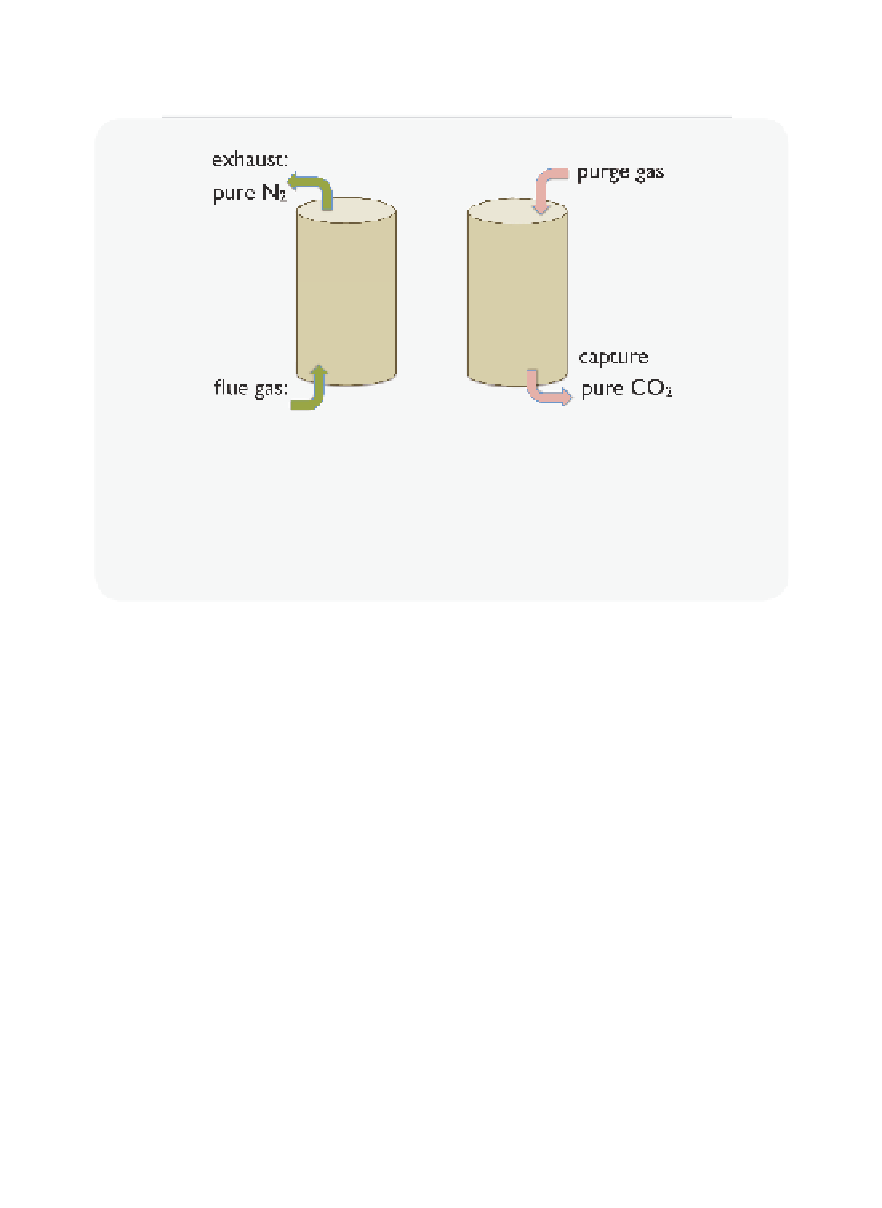
Figure 6.2.1
Fixed bed adsorber
In a fi xed bed adsorber, CO
2
is captured in two steps. In the fi rst step (left fi gure), the
CO
2
is selectively adsorbed from the fl ue gas. This adsorption bed needs to be regener-
ated once it is saturated with CO
2
. The fi gure on the right depicts the second regenera-
tion step, in which pure CO
2
is produced. In this step, the bed is heated and a purge gas
displaces the adsorbed CO
2
.
Fluidized bed adsorption
A disadvantage of fi xed bed adsorption is that it is a batch process,
meaning that the process must be interrupted periodically to change the
direction of the fl ow. In industry there are many good reasons to prefer
using a continuous process. For example, a coal-fi red power plant can-
not be shut down just to accommodate the replacement or regeneration
of an adsorption unit. Therefore, we need to run two adsorbers in parallel;
one in adsorption mode and the other in regeneration mode. This is not
always the most effi cient way to operate an adsorption process. Fluidized
bed adsorbers were developed to use solids in a continuous process
confi guration so that the adsorption process proceeds without any inter-
ruptions, just like the power plant. These fl uidized beds are very interest-
ing from the perspective of fl uid dynamics, and a great deal more
complicated from an operational point of view.
Transportation is the root of the problem. To have a continuous pro-
cess, we need to move our adsorbent from one place to another. Many
adsorbents are powders, which are particularly challenging to transport.
Imagine, if you will, trying to move 600 pounds of loose baby powder
several yards and back without spilling. It wouldn't be easy. Yet this is


Search WWH ::

Custom Search