Environmental Engineering Reference
In-Depth Information
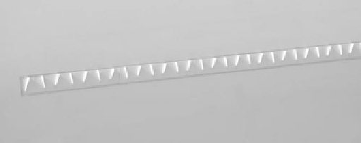
FIGURE 8.23
Shape and orientation of vortex generators on blade of GE wind turbine (77 m diameter, 1.5 MW).
8.9.3 V
ORTEX
G
ENERATORS
A vortex generator mixes the faster-moving laminar flow with the boundary layer, which delays flow
separation from the blade and stall. Typically there are counterrotating pairs of vortex generators on
the low-pressure side of the blade, with o 20° angles of incidence at 10% chord on the inner portion
of the blade (Figure 8.23), which is thicker and more prone to dynamic stall. Vortex generators were
installed on the MOD 2 and the MOD 5 wind turbines, and the performance was improved [31]. A
Carter 25 wind turbine has an optimal blade with a large amount of twist and taper at the root. When
vortex generators were tested on the unit, the maximum power was increased; however, power below
the rated wind speed was reduced because of the added drag of the vortex generators. In other words,
the inner portion of the blade did not enter stall and did not need the vortex generators. In general,
vortex generators improve blade performance by 4-6%. A unique concept is air-jet vortex generators
[32], which in wind tunnel tests gave an improved performance over the vane vortex generators. They
were installed on a 150 kW wind turbine and increased the maximum power; however, the potential
benefits were not conclusive, probably due to the placement of air-jets on the outer part of the blade,
rather than on the inboard section. Production blades now have vortex generators (Figure 8.24).
8.9.4 F
LOW
V
ISUALIZATION
The performance of blades, rotors, and towers can be checked by flow visualization: smoke, tuffs,
stall flags, pressure-sensitive liquid crystals, and oil streak. Tuffs are driven by frictional drag, while
FIGURE 8.24
Vortex generators on inner portion of blade of GE wind turbine (77 m diameter, 1.5 MW).

Search WWH ::

Custom Search